The H2HC 2018 Badge is small custom batch of bottle shaped PCBs. For an appropriate finish, the contacts are covered in real Gold!
While this real gold part might sound impressive, it’s a typical process for finishing PCBs called “ENIG” ( Electroless Nickel Immersion Gold ). During which the surface of all contacts is initially coated with nickel and then covered by a 5µm to 8µm layer of gold. (Just for comparision an 80g sheet of paper has a thickness of 128µm or 0.128cm). The aim of this gold coating is usually to create a super even surface for the placement of SMD parts, for us, well it’s a sweet contrast to the black PCB!
| Front | Back |
|---|---|
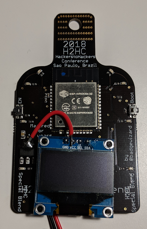 |
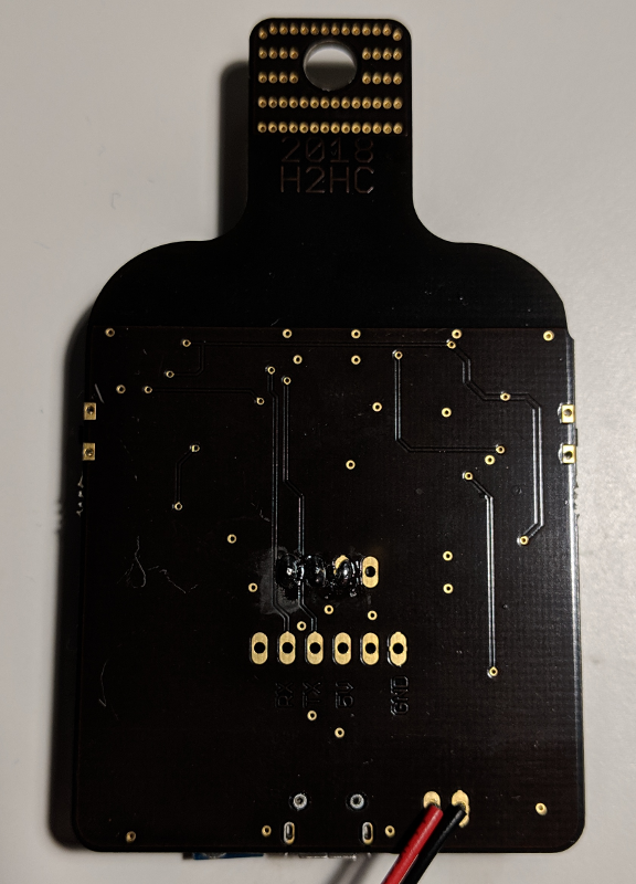 |
The Components
Main Controller
The heart and brains of the 2018 badge is an Espressif ESP32 WROOM , which is a small WiFi & Bluetooth LE System on Chip. I chose this specific SoC simply as my favorite supplier Watterott Electronics was able to make me a great price for it. Also these SoCs are highly flexible and can be used for many many different projects! Depending on what you’re doing, they can also be programmed using MicroPython or node.JS/low.JS . While using a language like this on an embedded device is real fun and great for learning, it simply has far too much overhead when wanting to run the device of batteries. And as the attendees already noticed, the BLE functionality itself does suck the life out of batteries when running the whole time!
Display
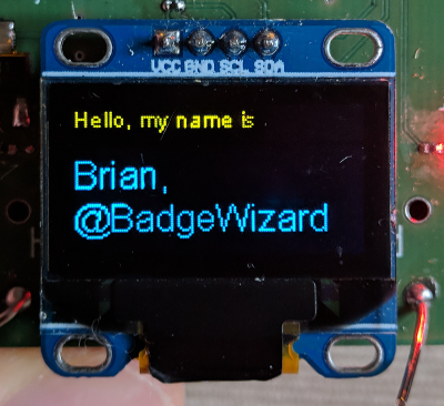
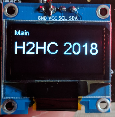
The devices Display is a simple 0.96" I2C OLED display. The best way to find them is just using Google and searching for 0.96" i2c OLED, then just have a look at the first few entries. It is important to note that these displays come in many different flavours. i.e. my prototype displays had a coloured bar at the top and had blue writing, the final ones for H2HC had white text. Also the VCC and GND pins on the final displays where swapped, as such the slightly ugly soldering some of you might have noticed.
Still, as far as I’ve seen the displays you find with that search term should all be compatible.
| Beta Display | Final Display |
|---|---|
 |
 |
Power Supply
The badge can run off 3 AAA batteries, depending on whether you use WiFi, BLE, just the displays, just LEDs the battery life will vary significantly. Alternatively the badge will also run off the USB port at the base of the Badge.
Programming
IDE
The code on the Badge was written in the Arduino IDE . To get everything up and running you will have to follow the instructions for installing the ESP32 extensions . You will also need the ESP8266 and ESP32 Oled Driver for SSD1306 display library, which can be installed via the Arduino IDE library manager ( Tools -> Manage Libraries… ).
Settings
- Board: ESP32 Dev Module
- Upload Speed: 921600
- Flash Frequency: 80MHz
- Flash Mode: QIO
- Flash Size: 4MB (32Mb)
- Partition Scheme: Default
And be sure to select the correct USB port.
Connector
For programming the badge, you will need a USB to serial adapter. My standard cable is an FTDI TTL-232R-5V, which we here always just call an “FTDI cable”. Of course other USB to serial adapters will also do the job.
If you should have an H2HC 2015 Badge or any other Arduino you can also use this as a programmer. To do so, just open the Arduino IDE, click File -> Examples -> 04. Communication -> SerialPassthrough and connect the RX and TX pins to the badge.
As @nataschenka found out the hard way during the conference, there a few current issues with a kernel module and FTDI chipsets….
Warning :)
DO NOT USE THE USB TO SERIAL ADAPTERS YOU’D USE FOR A CISCO SWITCH etc.!! These usually provide 12V and will fry the badge! If you’re not sure, get an adapter with TTL in the name.
Code
In general the code is based on the example code coming with the ESP32 libraries, which is available in the Example section of the Arduino IDE.
A copy of the code can be found here: Code Archive
Defines
The Badge comes with 6 controllable LEDs which are connected to the following pins:
#define LED1 16
#define LED2 22
#define LED3 23
#define LED4 25
#define LED5 26
#define LED6 27
Using I2C for the display, these lines also need to be initialized:
#define D3 4
#define D5 5

SSD1306Wire  display(0x3c, D3, D5);
BLE
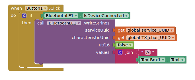
The interesting function here is void onWrite(BLECharacteristic *pCharacteristic). It uses a switch case command for interpreting the input coming in via BLE and then switches LEDs or shows text messages on the display.
BLE App
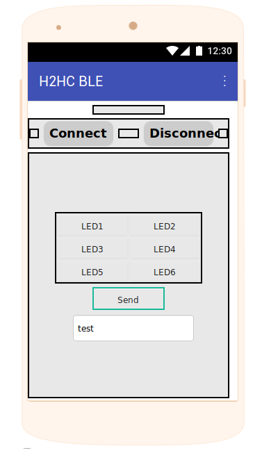
For a simple way to interact with the BLE functionality I had a look at some instructions on hackster.io . The example uses a webservice called thunkable to create a simple dynamic Android app being able to use BTLE.
Being a very simple and straight forward example, I expanded it slightly to fit the Badge’s requirements.
As a short preview:
The project can be found here .
Simply log into thunkable and import the file.
Display
To play with the display, you should open the display tab in Arduino IDE and have a look at the code there.
The code currently has 5 tabs:
- Main Page, showing “H2HC 2018”
- Dev status page
- Last message page, showing the last message that came in via BLE
- Debug page, showing the last raw text that came in via BLE
- Name page, showing the name set on the badge
New tabs can easily be added by copying one of the existent pages and expanding the void display_loop() function.
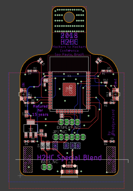
The PCB