Logic analyzers play a crucial role while analyzing hardware, circuits and components. The core use case is sniffing the communication between two components (i.e. a controller and a sensor, controller and memory). The word “logic” results from the fact that the LA eventually shows 1s and 0s. While an oscilloscope will show the actual flow of the voltage on an input. The LA compares the voltage against a defined threshold, everything above is a 1, everything below a 0. The period in which these measurements are made are set by the sample rate (sometimes simply called speed). For USB LAs the collected data is then temporarily stored in the LAs local memory or directly streamed into the host systems RAM. The actual visualization of the information is usually only done after a defined set of samples (individual reads) have been performed. The user then has a plot which can be analyzed hand or automatically.

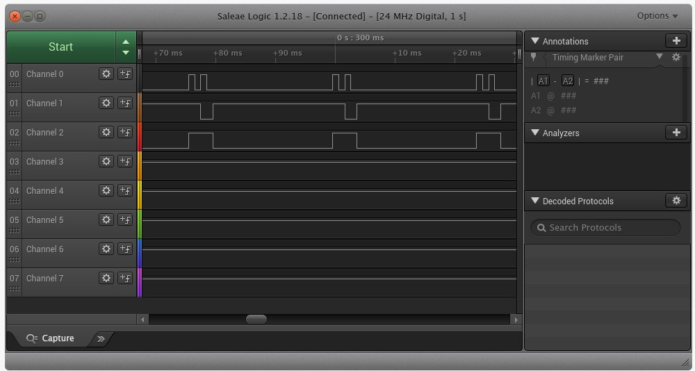
The picture shows information from two Channels (the channels 2 and 3). Channel 2 shows a clock (clk) line, which periodically alternates and as such tells the communication partner when it has to read from the data line. The actual data is on channel 3. The LA now allows us to read the bits which where transferred. To do so we read the data line for each time the Clock signal is high. Having four periods, we need to read four bits. In this case low, high, high, low or 0110.
Saleae
Saleae is a company / group of people that started by developing and crowd sourcing a neat little logic analyzer. From there on they’ve evolved to a integral part of the LA product field. While being worth the price, the devices sadly require a certain budget. After having bought a Logic Pro 16 in May 2017 for just under 700€, at the time of writing (beginning of 2018) they’re up to just over 1000€.
Above the hardware, Saleae also offers a (free) UI for the LAs.
While at first sight the UI might look too simple, it covers everything thats necessary! The channels can be shown/hidden on the left, the actual signals are in the middle and further features are on the right. Detailed examples will follow further down.
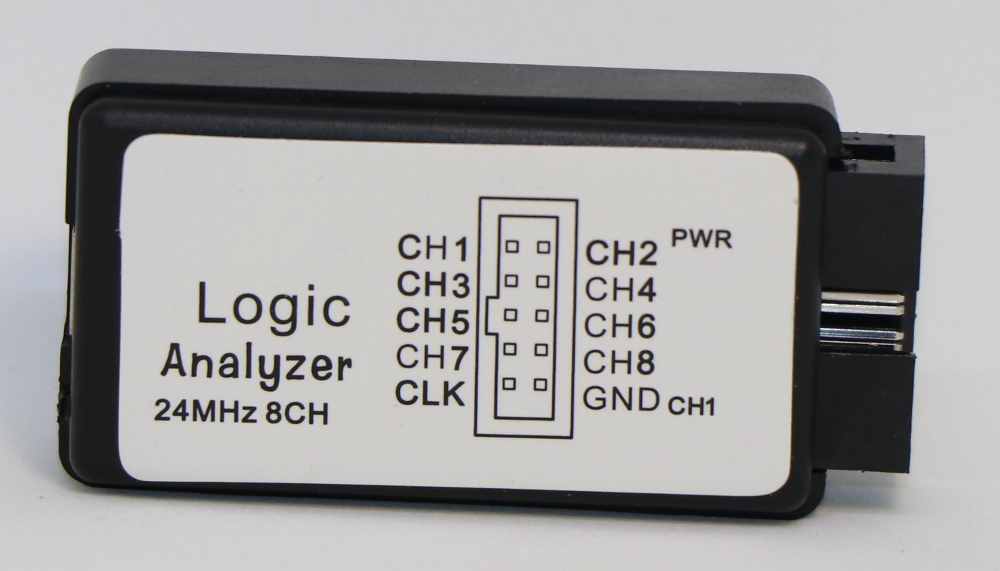
Cheap Chinese Logic Analyzers
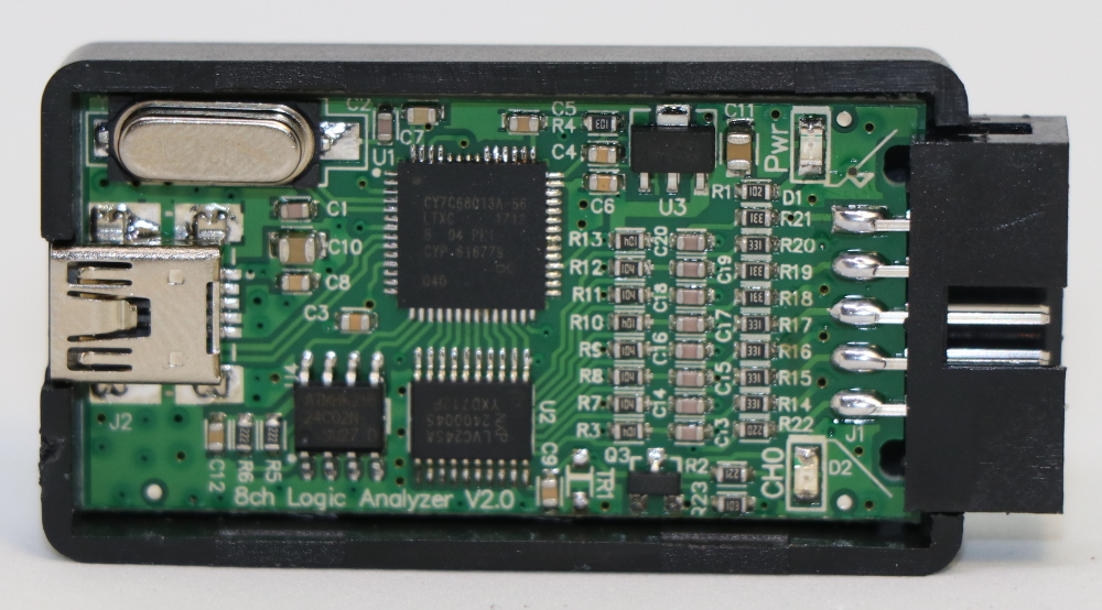
eBay, Alibaba, Amazon and what ever shop you might use will most probably have some kind of cheap China made LAs on offer. I’m using the phrase “Chinese” here, because they all seem to have the exact same case, very similar internals but all come from different small Chinese companies. They cost between 6€ and 25€, run at 24MHz and have 8 channels. After having had four or five different flavors in my hand, there seems to be one main difference between the flavors: The input resistors. A perfect LA would have an infinite input resistance, so that not a single electron gets lots due to measuring, practically they have a very very high resistance. In the world of electronic components, especially resistors, one has the choice to i.e. add four single resistors or use an integrated circuit which basically has eight connections and consists of four resistors in a single package (reduction of parts). Although in general the combined resistors are just as good as the single ones, it was my experience that the LAs with the combined resistors did a really bad job. In certain situations communication broke down completely, as such the resistance in the LA seems to have been too low. (“Experience”: About 25 devices from three different sources ordered in three batches. Different labels and slightly different parts in use. Can’t say whether they came from the same production line…)
Obviously they aren’t the best, but they’re cheap, do the job and are compatible with the Saleae software!
Sniffing Asynchronous Serial
Some people call these interfaces UART (Universal Asynchronous Receiver-Transmitter) , some just say “serial”, others say RS-232 . Although often mixed up, RS-232 actually is “only” a practical UART implementation. A significant aspect here being the used voltage levels. While the UART interfaces on most microcontrollers run at voltage levels between 1.8V and 3.3V, RS-232 often runs at 5V oder 12V (it’s defined to run between 3V and 15V). As such if you grab your “USB RS-232” adapter, as you use to configure your switches, this adapter might very well fry your microcontroller target device. Back to the actual topic: For the rest of this overview I’ll simply stick to the term “serial”, especially as the practical implementation doesn’t make a big difference for the analysis. (Just make sure that your LA can take the input voltage!)
Most LA UIs offer protocol decoders or analyzers. These will run the recorded information through a piece of code and try to extract the actually transmitted information.
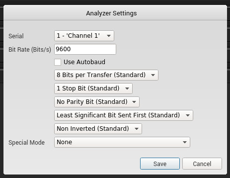
Initially the channel needs to be selected. Above that the “Autobaud” function does work reliably for in most cases. (Although, especially when working with slow low power devices it will often have trouble detecting the baudrate as the signals will by far not be symmetric.)
 {:width=“100%” .center-image}
 {:width=“100%” .center-image}
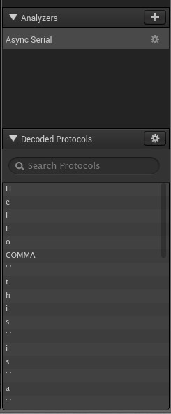
The UI also gives you the extracted information in a nicely exportable format.
 {:width=“40%” .center-image}
HowTo Test
For the first steps with an LA it is always easier to try to decode a known signal. For described example I used a Arduino Leonardo with the following program.
void setup() {
  // put your setup code here, to run once:
  Serial1.begin(9600);
}

void loop() {
  // put your main code here, to run repeatedly:
  Serial1.write("Hello, this is a test");
  delay(1000);
}
sniffROM
sniffROM is an Open Source Python script that will use a communication sniff and create a binary image of a memory chip. When reading from a memory chip (FLASH, ROM etc.) via SPI or I2C the communication consists of commands and payload data. One of the most important commands here is a simple read command. The script will analyze a CSV dump of a sniff on the data lines between a controller and a memory chip and extract all read / write commands and work out which data is stored at which offset. As such, by parsing the sniff, an image is created. Of course the image might not be complete, as the script only has information on offsets which were accessed in the sniff.
Clips (I don’t know how to call this section)
When sniffing communication from chips the first question is: How do I access the data lines? The trivial approach would be soldering, if you can and want to. The next approach would using something like Blu Tak and jumper wires, which works but is rather unstable. The nicest approach is using a clip. I guess pictures are the easiest explanation.
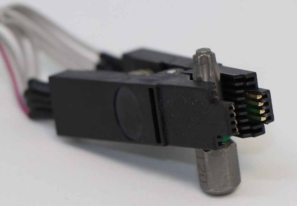
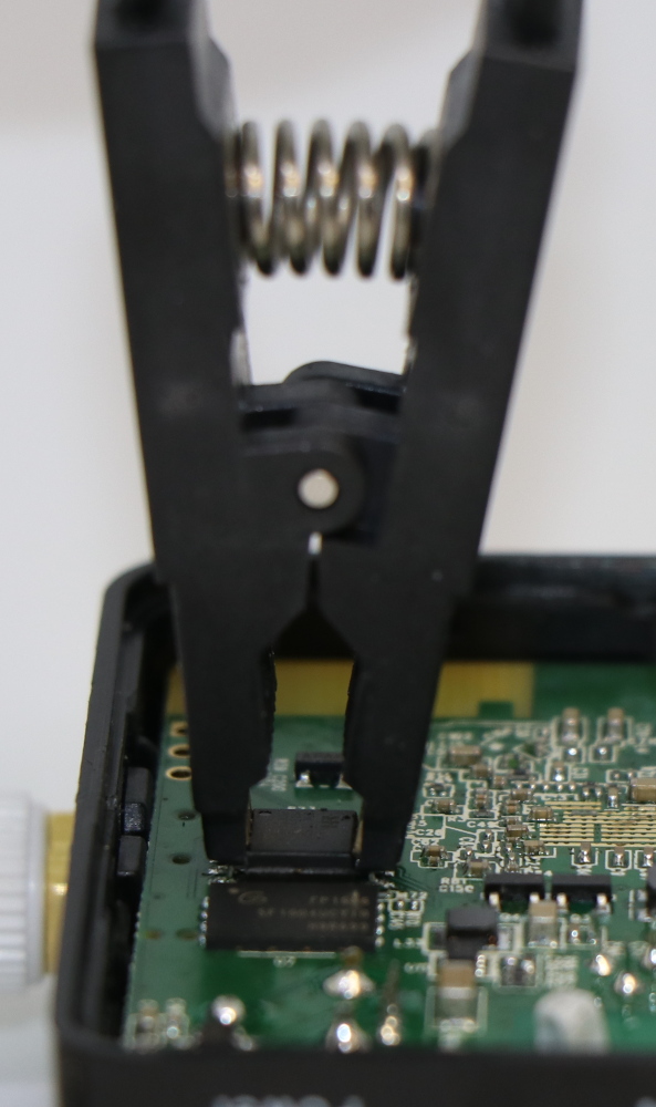
These clips are usually called SOIC Clip or SOP Clips or programming clips and cost between 5€ and 50€. I’ve tried clips for about 10€, 25€ and 40€ and and all off them were equally good and did the job. They usually die because the small plastic tips which go in between the pins twist or break, which happens to the clips in all price ranges. As such I’d rather go for a cheap one and replace it from time to time, rather than having clips that flip off and create shorts somewhere in a running device.
Reading Bits, Code
Here is the code that was used to generate the very first example.
#define clk 2 //clock
#define data 3

void setup() {
  // put your setup code here, to run once:
  pinMode(clk,OUTPUT);
  pinMode(data,OUTPUT);

  digitalWrite(clk,LOW);
  digitalWrite(data,LOW);
}

void loop() {
  // put your main code here, to run repeatedly:
  // Sending 0110
  //bit 0
  digitalWrite(data,LOW);
  digitalWrite(clk,HIGH);
  delay(5);
  digitalWrite(clk,LOW);
  delay(5);
  //bit 1
  digitalWrite(data,HIGH);
  digitalWrite(clk,HIGH);
    delay(5);
  digitalWrite(clk,LOW);
  delay(5);
  //bit 2
  digitalWrite(data,HIGH);
  digitalWrite(clk,HIGH);
  delay(5);
  digitalWrite(clk,LOW);
  delay(5);
  //bit 3
  digitalWrite(data,LOW);
  digitalWrite(clk,HIGH);
  delay(5);
  digitalWrite(clk,LOW);
  delay(20);
}