The H2HC 2022 CTF
I recently ran a hardware based CTF at H2HC in Brazil. As the CTF was to run for two days, it was setup in two phases, where each of them had tasks that could be solved independently and others that need hints from other challenges. Sadly, the challenges were seemingly far to hard for most of the attendees and the winning team only managed to extract 5 flags. Here is the complete writeup and guide for the CTF.
Overview
Being inspired by Bryan Fite’s PacketWars approach the CTF followed a rough story line: The players work in forensics, get a bunch of evidence that got mixed up and would have to work their way through it. Day 1 would cover some physical evidence, various electronics, and day 2 would cover crimescene pictures, and a few more side challenges and hints. Following this topic, the players received evidence sheets to submit the flags and bring them into context with the evidence. I would have loved to have done a full scale story based scenario, but as my Portuguese isn’t notable and I know a few of the players in Brazil aren’t fluent in English, using classical flags in combination with simple hints felt like a good compromise to create a red line. As, in addition, I quite enjoy all these Escape board- and card-games they also had an influence on the idea.
The CTF and its challenges are aimed at players who have done CTFs before, enjoy gaming and enjoy learning something new. While not requiring a lot of Hardware/Embedded knowledge, it requires a fair amount of strategy, as is also necessary during a typical pentest, while doing security research, or when playing a big CTF. Also the game contains a lot of flags to on the one hand make sure all players in the teams have something to do and that if one flag fails, maybe the players would manage a different one in return.
The writeup is still missing details for three of the challenges, which will follow in the next few days
CTF Summary
At the end of the CTF we received 3 submissions with flags. The highest amount of identified flags was 6 valid ones. In addation two a few incorrect ones. So from the large amount of 32 hidden flags, well 6 is a little bit sad.
Interestingly a few players just joined, gave a few challenges a try and didn’t even want to submit their flags, but just learn something new. Which in return was really nice!
All in all the overall result of 2, 4 and 6 flags was pretty sad…….
All files and challenges from the CTF will be uploaded to GitHub in the next few days and the link both added here and shared via Twitter. Just didn’t want to let you wait any longer!
On Site Changes
As the CTF had a very hard start and teams even decided not to even try hardware based challenges, the story was dropped and I went for a simple “work your way through the stuff and give me some flags”. As such the players also got a bunch of hints and help to move into the right direction. Also, the scoring system, described further below was dropped, as it had no influence on the game. In addition, with the not very nice results of the CTF, this writeup is being expanded into having by far more details than planned, to function as a starting point for the players next CTFs.
Strategy Guide
The same as with every Pen- or Security-test one always starts with a recon phase. As such the players should have a look at everything they have and create a list of parts/components, their names and if known their type/function. I.e. one entry might be chip, black, 8 pins, "24LC01B-I/P". This way the players have both a checklist to make sure they didn’t forget anything, but at the same time not everybody has to pick up every small part to read the writing on there but can work from the list. From this point the typical recon steps of collecting information starts. As such the players should start using search engines to find out, what kind of components their dealing with, what their properties are and how they can be utilized. Searching for the 24LC01B-I/P for example, one will quickly see that it is an EEPROM. If the abbreviation is unknown, a search engine will help and result in Electrically Erasable Programmable Read-Only Memory. Knowing it’s memory and knowing one is looking for flags, reading the memory might be a good idea. Thus, collecting more details and then carrying on search with each of the new parameters is a very quick way of learning how to get started with strange things.
This strategic approach especially also applies when new details are added. On day two of the CTF, the players received an envelope with a USB stick. Thus, the teams should take a short break from their current hacks and return to the recon phase for the newly received parts/components and data. Especially when playing story based games, new data will very quickly answer questions one previously had. I.e. if you have 10 NFC cards but don’t know in which order you have to bring the information on them, a picture on the USB stick might very simply be the solution.
Challenge Types
The CTF consists of challenges of various types and are sorted by these in the writeup. The first and most important type are the Hardware challenges. As the CTF is aimed at being a hardware based CTF, these challenges give the most points and will be the newest to the players. The second type are the Side challenges, which are a few random tasks / flags that reward thoroughness and bring little bit of surprise into the game. Then there are the USB flags, which just bring a little bit more variety into the game and make sure everybody has something to do during day two of the CTF. The last type are the Evidence challenges, actually it’s a single challenge bringing multiple points.
Tools
To be able to solve the challenges the players receive two tools, an Arduino Nano and an ESP32 with MicroPython pre-installed. Both boards come AZ-Delivery, a shop that offers pretty cheap and so far, always reliable boards. As there always is a big chance of physically breaking / bricking devices while learning with the, I tend to buy cheap alternatives.
Arduino Nano
The easiest way of getting started with the Arduino Nano is by downloading the Arduino IDE. It offers you all necessary libraries and functions.
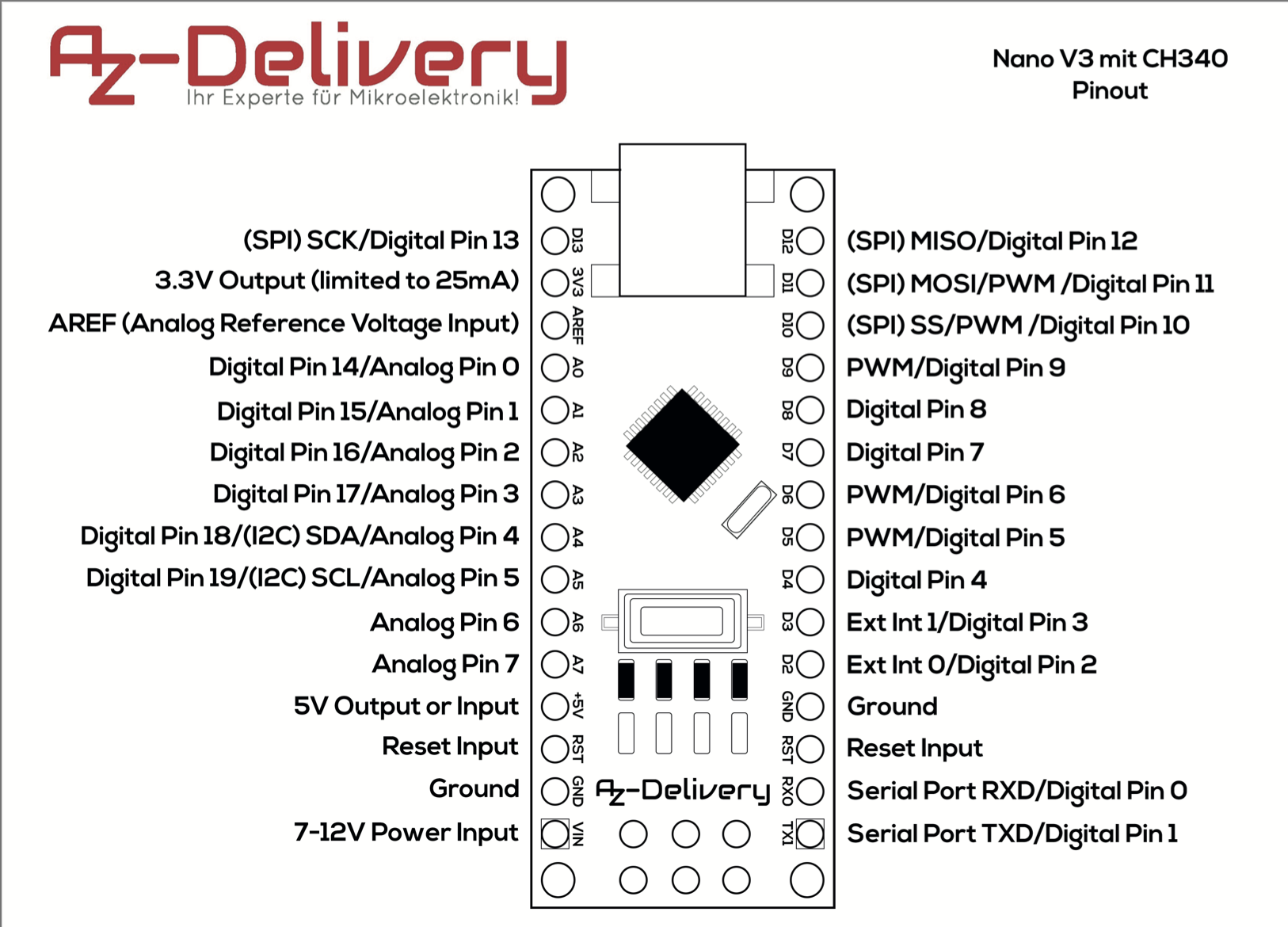
The board used during the CTF is a Nano V3.0 with ATMEGA328 CH340 from AZ-Delivery.
Here is the pin-out for future reference.
ESP32
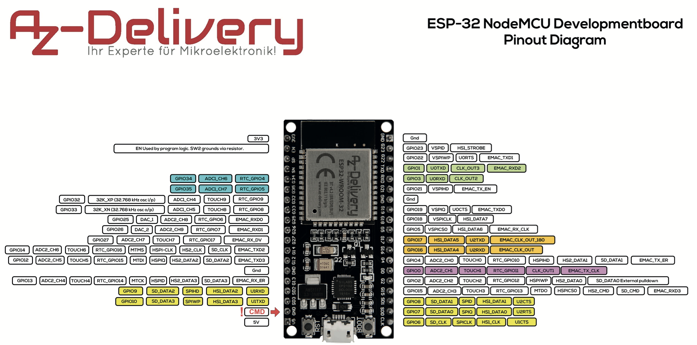
The ESP32 board is actually a ESP32 NODEMCU Module WiFi Development Board with CP2102 from AZ-Delivery. As mentioned before it comes preloaded with a current version of MicroPython. This simply is the way I tend to use it, and thought it might offer a quick start for player who know their Python.
The easiest way to copy files to and from the ESP32 is ampy, a tool by Adafruit. Here an example:
ampy --port /dev/ttyUSB0 put bla.py
Most other details can be directly read from the MicroPython manuals, various tutorials and examples. One will very quickly see…it’s Python…
Here is the pin-out for future reference.
Flag Format
- H2 or HC
- 1 opening symbol + or -
- 3 letters
- 3 digits
- 3 capital letters
- 3 digits
- 1 closing symbol + or -
- CRC16 in 4 capital letters and digits
Regex
((H2)|(HC))(+|-)[A-z]{3}[0-9]{3}[A-Z]{3}[0-9]{3}(+|-)([A-Z]|[0-9]){4}
CRC16
The CRC16 checksum is calculated as follows:
import crc16
...
cs = crc16.crc16xmodem(flag.encode('utf-8'))
Day 1: The Plastic Box
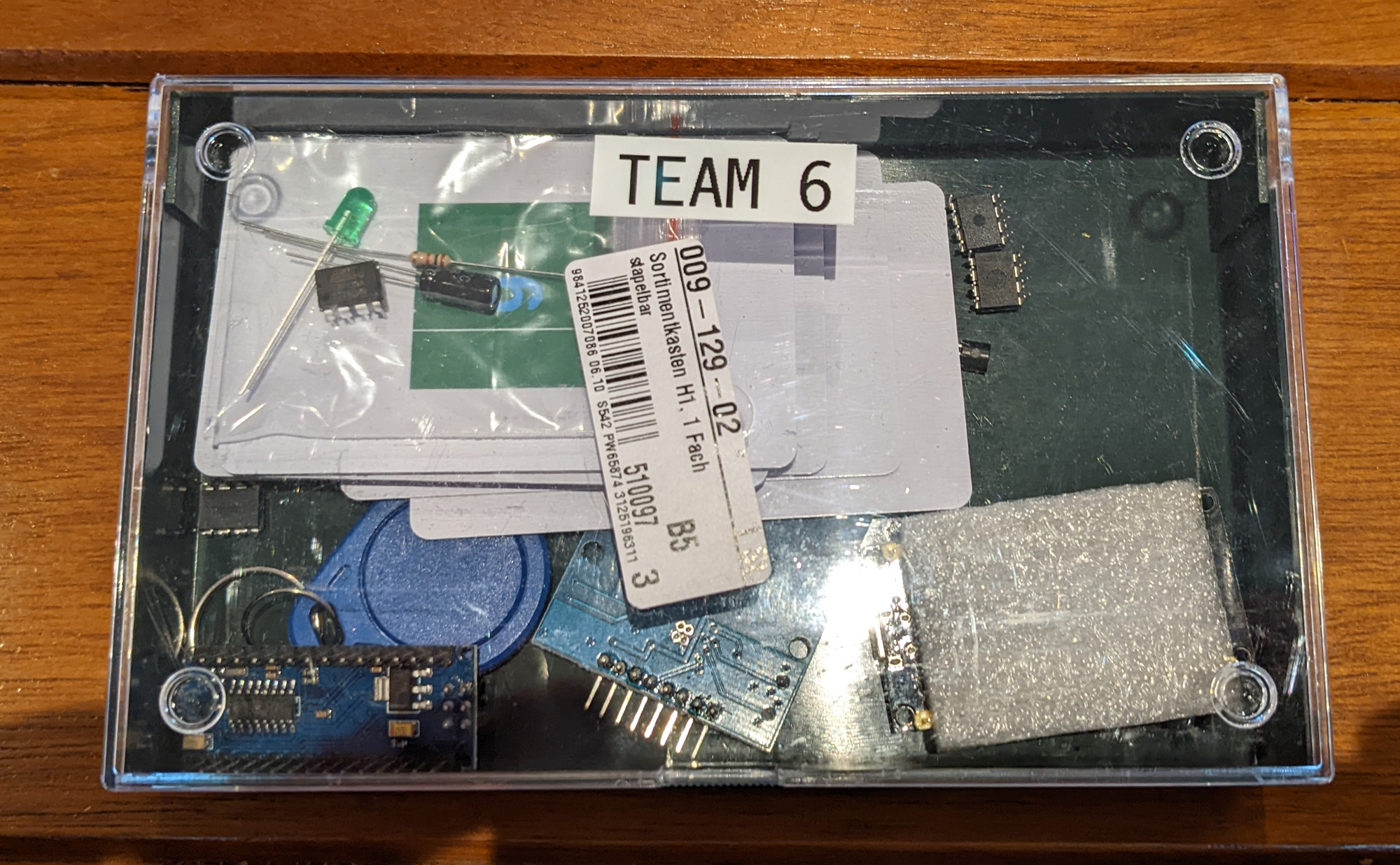
On day 1 the players received a green plastic box containing the following parts
- An EPS32 with MicroPython preinstalled
- An Arduino Mini (based on the UNO with an ATMega328p)
- And a Mini-USB cable, as I figured “normal” Hackers don’t have them anymore
- An RFID-RC522 NFC shield / module
- A small plastic bag with an ATTiny13A-PU
-
- a capacitor
-
- a resistor
-
- LED
-
- An 24LC01B-I/P, I2C EEPROM
- An 93LC46C-I/P, SPI EEPROM
- An 11LC010 DIP, Microchip Single Wire EEPROM
- An 11LC010 TO-92, Microchip Single Wire EEPROM
- A blue MifareClassic NFC dongle
- 10 MifareClassic NFC cards
- A breadboard
- A bunch of jumper wires
Day 1 challenges
H1: I2C Memory Chip / 24LC01B-I/P
The I2C chip contains a simple ASCII encoded flag. Thus, the main challenge is to connect the chip to either the Arduino or the ESP32 and read the data from it.
The chip also contains a hint for challenge U2 as in the String PW: Mn58Jdfq4! and the String “CISCO” as reference to E1.
The content is as follows:
00000000: 4349 5343 4ff9 40af afb2 0838 2f0e 568c  CISCO.@....8/.V.
00000010: 2b2b f782 e4c9 e831 c1ff 0e62 21bd 7648  ++.....1...b!.vH
00000020: 6364 41dd 40af a11c 23c5 b3ae f0d4 7025  cdA.@...#.....p%
00000030: 0bab 989f f1cd d16f bf16 de72 152f 4e48  .......o...r./NH
00000040: 432b 4b4a 5733 3733 5947 5831 3035 2d46  C+KJW373YGX105-F
00000050: 4145 38db bc3e bba7 de09 6121 1ef2 0511  AE8..>....a!....
00000060: d49a c15e bc49 c737 0231 a069 0bde 18ef  ...^.I.7.1.i....
00000070: e771 5057 3a20 4d6e 3538 4a64 6671 3421  .qPW: Mn58Jdfq4!
To solve this challenge, players would initially have to identify the chip and find out what it does. The chips’ name/type can be found directly on the chip. Now searching for 24LC01B-I/P will result in a lot of different results, from shops over tutorials to the manufcaturer’s website. The website can be confirmed as it contains the same logo as is printed on the chip. By either reading the data directly on the site or downloading and reading the datasheet one quickly finds all important information about the chip 1K I2C Serial EEPROM This it has a capacity of 1kbit and runs on the I2C bus. Looking a little bit further one also finds a pinout diagram of the chip. Even though at this point it isn’t helpful yet, it’s good to know.
Yet again using a search engine, and searching for something like arduino read i2c eeprom one finds a lot of different tutorials. Some on [GitHub[(https://github.com/DMRodrigues/arduino-i2c-read-eeprom){:target=”_blank”}, some on the official Arduino website and very many others. One of these is the tutorial from maker.io, which I’m using know as it is really short and simple.
The first important image is the wiring diagram. It shows how to connect the Arduino with the 24LC01B-I/P.
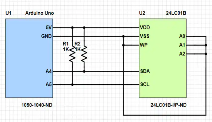
- VCC or VDD or
+: To supply power and also usually a logical one - GND or VSS or
-: Ground is the second part of the power supply and a shared potential. Also usually a logical 0 - SCL:
Serial Clockwhich synchronizes the chip and the arduino while transmitting data - SDA:
Serial Datawhich actually transmits the data - WP:
Write Protectwhich prevents accidental writing to the chip - A1, A2, A3: The address lines. As I2C is a bus, there has to be a way to select a specific component on the bus one wants to talk to.
Following the tutorial, the lines A1, A2, and A3 are connected to GND, which means the address field is set to 000. As the tutorial is about both reading and writing the WP pin is also connected to GND / 0. As long as no write command is sent, it doesn’t make a difference.
The SCL and SDA pins are a little bit challenging, as they go to specific pins on the Arduino Uno in the tutorial. While the Arduino Nano and the Uno are both based on the Atmel328(P), the boards are different and the pins in other orders. Luckily the I2C pins on the Uno and on the Nano have the same names. As such the pins A6 and A7 can also be used on the Nano from the CTF.
The design from the tutorial shows two pullup resistors from SDA and SCL to VCC. I honestly forgot to pack these two resistors into the box, and thus kept them at my desk to see whether anybody actually got so far. Only one player did, but was also just playing for fun.
From here one just as to use the bread board or flywires to connect the Arduino and the EEPROM, load the code with Arduino IDE and adjust the read code a little.
H2: SPI Memory Chip / 93LC46C-I/P
The SPI memory chip yet again contains a flag, but in a slightly strange encoding. A few years ago a friend and I found a filesystem, where the nibbles of each byte where swapped. Thus the character A, 0x41 or 0100 0001 in binary would have been 0x14 or 0001 0100. On the original system, we understood the data due to a data set looking like this 1032547698BADCFE at the start of the memory. For this challenge the data on the chip ends with the exact same pattern. Only being 125 bytes long, it was expect that the combatants would be able to actually read through the whole of the data and find the hint.
This is what a quick decoder can look like.
in_file = open('challenge.bin', 'rb')
out_file = open('decoded.bin', 'wb')

res = bytearray()
for d in in_file:
    for c in d:
        res += ((c & 0x0F) << 4 | (c & 0xF0) >> 4).to_bytes(1,"little")

out_file.write(res)
out_file.close()
in_file.close()
The binary content looks as follows:
00000000: 29b7 5052 a6e2 1866 98e5 07db 8434 d286  ).PR...f.....4..
00000010: 9554 1323 83c4 4565 5343 93d2 1444 1463  .T.#..EeSC...D.c
00000020: 7fac 23a7 7256 1674 bd29 2973 15b8 4fb2  ..#.rV.t.))s..O.
00000030: a56d fd12 cd70 4235 b982 b262 6210 645a  .m...pB5...bb.dZ
00000040: f619 bc06 7cc5 c277 d6e1 5bb7 4767 328f  ....|..w..[.Gg2.
00000050: c6ed f53c c4da a218 5c66 32cf e2b8 a57d  ...<....\f2....}
00000060: ddcc 5d1c 8133 5384 81e4 13f8 162e 5cc3  ..]..3S.......\.
00000070: 4541 3370 0e3c 1dbf 1032 5476 98ba dcfe  EA3p.<...2Tv....
To solve this challenge one can follow the instructions from the I2C EEPROM. During the inital recon phase, the players will find out the 93LC46C-I/P is an EEPROM for the Microwire bus. Here lies the first little challenge. The Microwire bus is fully SPI compatible, which is stated in a lot of sources. Thus to access this chip one has to find a way to read an EEPROM using the Serial Peripheral Interface. One nice tutorial can be found on the Arduino Website.
SPI needs a few wires more than I2C:
- MOSI:
MasterOutSlaveIn - SPI bus in cotrolled by one component, the bus master. In our case this is the Ardunio.The MOSI line transmitts data from the Master to the Slave, like a TX line. - MISO:
MasterInSlaveOut - The opposite direction, from the slave to the master - CLK:
Clock- The clock line, synchronizing the slave with the master - !CS:
NotChipSelect - Being a bus, the master can be connected to multiple slaves.The !CS line is used to select the currently used slave. The!or not means the line is inverted. Thus it’s by default set to a logic1and pulled down to0if the chip is to be used.
The connection diagramm shows which pins need to be connected. As mentioned before, the CTF used an Arduino Nano and not an Arduino Uno. Thus the pins have tobe adjusted to the pinout of the Nano.
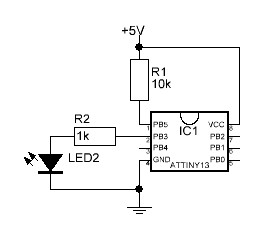
H3: ATTiny / ATTINY13A-PU
The ATTiny comes in a small bag with a LED, a resistor and a capacitor. The chip is programmed to transmit a flag in morsecode on pin PB2 / 7. Only having 8 pins, two of which are the power supply and on the !Reset line, there aren’t many options to attach the LED.
The firmware looks like this
//Based on the ATTiny13 blink demo

#include <avr/io.h>
#include <util/delay.h>
int main(void)
{
DDRB |= 0x04;
uint8_t ds = 500;
while(1)
{
_delay_ms(2000);
Short();
Short();
Short();
Short();
Long();
Short();
Long();
Short();
Long();
Short();
Short();
Short();
Short();
Long();
Short();
Long();
Long();
Short();
Short();
Long();
Short();
Long();
Long();
Short();
Long();
Long();
Long();
Long();
Long();
Short();
Short();
Short();
Short();
Short();
Short();
Short();
Long();
Long();
Short();
Long();
Short();
Short();
Long();
Short();
Long();
Short();
Short();
Short();
Short();
Long();
Short();
Long();
Long();
Long();
Long();
Short();
Short();
Short();
Short();
Long();
Short();
Short();
Short();
Short();
Short();
Long();
Short();
Short();
Short();
Short();
Long();
Long();
Long();
Long();
Long();
Long();
Long();
Short();
Short();
Short();
Short();
Long();
Long();
Long();
Long();

}
return 0;
}
void Short(void)
{
PORTB |= 0x04;
_delay_ms(500);
PORTB &= ~0x04;
_delay_ms(250);
}
void Long(void)
{
PORTB |= 0x04;
_delay_ms(1000);
PORTB &= ~0x04;
_delay_ms(250);
}
Having been lazy, I hacked together a Python scrip to generate the firmware:
code = open('morse.ino', 'w')

plain_text = "HC-PEY163LCV145-0DE1"

mcd = { 'A':'.-', 'B':'-...',
                    'C':'-.-.', 'D':'-..', 'E':'.',
                    'F':'..-.', 'G':'--.', 'H':'....',
                    'I':'..', 'J':'.---', 'K':'-.-',
                    'L':'.-..', 'M':'--', 'N':'-.',
                    'O':'---', 'P':'.--.', 'Q':'--.-',
                    'R':'.-.', 'S':'...', 'T':'-',
                    'U':'..-', 'V':'...-', 'W':'.--',
                    'X':'-..-', 'Y':'-.--', 'Z':'--..',
                    '1':'.----', '2':'..---', '3':'...--',
                    '4':'....-', '5':'.....', '6':'-....',
                    '7':'--...', '8':'---..', '9':'----.',
                    '0':'-----', ', ':'--..--', '.':'.-.-.-',
                    '?':'..--..', '/':'-..-.', '-':'-....-',
                    '(':'-.--.', ')':'-.--.-'}

mc = ""
for c in plain_text:
    mc = mc + mcd[c] + ""

print(mc)

# Static content
code.write("//Based on the ATTiny13 blink demo\n\n")
code.write("#include <avr/io.h>\n")
code.write("#include <util/delay.h>\n")


code.write("int main(void)\n{\n")
#Define pin as output
code.write("DDRB |= 0x04;\n")
code.write("uint8_t ds = 500;\n")

code.write("while(1)\n{\n")

code.write("_delay_ms(2000);\n")
for c in mc:
    if c == '.':
        code.write("Short();\n")
    elif c == '-':
        code.write("Long();\n")
    elif c == ' ':
        code.write("_delay_ms(ds);\n")

code.write("\n}\nreturn 0;\n}\n")

code.write("void Short(void)\n{\n")
code.write("PORTB |= 0x04;\n")
code.write("_delay_ms(500);\n")
code.write("PORTB &= ~0x04;\n")
code.write("_delay_ms(250);\n")
code.write("}\n")

code.write("void Long(void)\n{\n")
code.write("PORTB |= 0x04;\n")
code.write("_delay_ms(1000);\n")
code.write("PORTB &= ~0x04;\n")
code.write("_delay_ms(250);\n")
code.write("}\n")

code.close()
Using a search engine to find details on the ATTINY13A-PU the manufacturer’s website and the applicable datasheet are the first stop. As the manufacturer of the ATTiny, Atmel, was bought by Microchip a few years ago, the logo on the chip and the website don’t match.
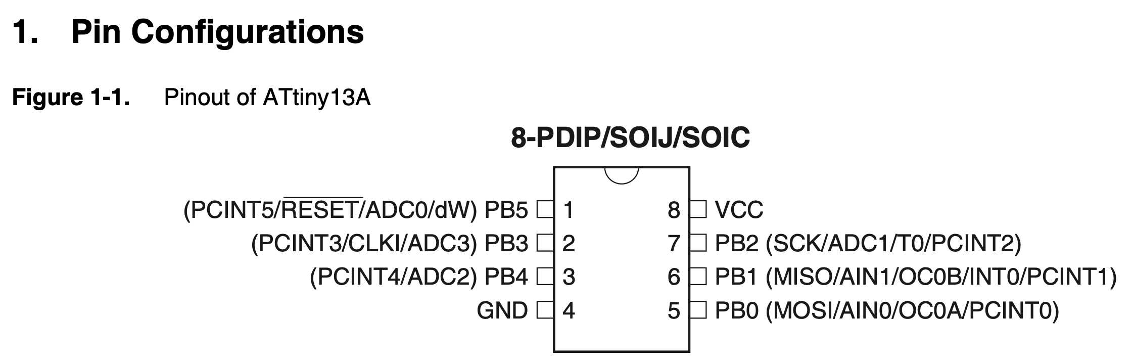
Searching i.e. for ATTiny13 LED, thus the main parts from the bag, one quickly finds a lot of tutorials like this one. All tutorials show the same basic setup.
VCC/+andGNDare the same as with the flash memoriesPB5/!RESETcan optionally be pulled up toVCCwith a resistor- The
!RESETline has an internal pullup resistor and as such is already set to logical1and will as such not reset by itself.
- The
- The capacitor from the bag is optional and can be connected between
VCCandGNDclose to theVCCpin.- The capacitor stabilizes the power supply for the chip.
Where to connect the LED is now the first challenge. With there only being 6 (5 if you don’t count !RESET) the players have to connect the LED to each pin and see where the LED actually does something.
From this point the players have to do their best at reading morse code!
H5: NFC Cards
Each NFC Card contains two bytes of the flag. The correct order can be derived from Evidence 2 and Evidence 5. The keys of the cards are simply sequences of letters on their print. Thus card A requires the key 0xaaaaaaaa. While not directly visible from a hint, some keys are default keys and one has a good chance of seeing the pattern.
Details will follow.
H7: Single-Wire EEPROM / 11LC010 DIP
The single-wire EEPROM in the DIP package yet again contains a simple flag. The challenge here lies in getting the Single-Wire protocol to work.
Both 11LC010 (H7 and H8) chips are expected to be last challenges to solved during the Hardware part of the CTF. Using search engines during recon yet again brings one to the manufacturers website and also to the datasheet. It’s yet again easy to see, that the chip is an EEPROM, but instead of using SPI or I2C it uses the Single I/O, UNI/O Serial Interface Bus. The pin-out is as follows.
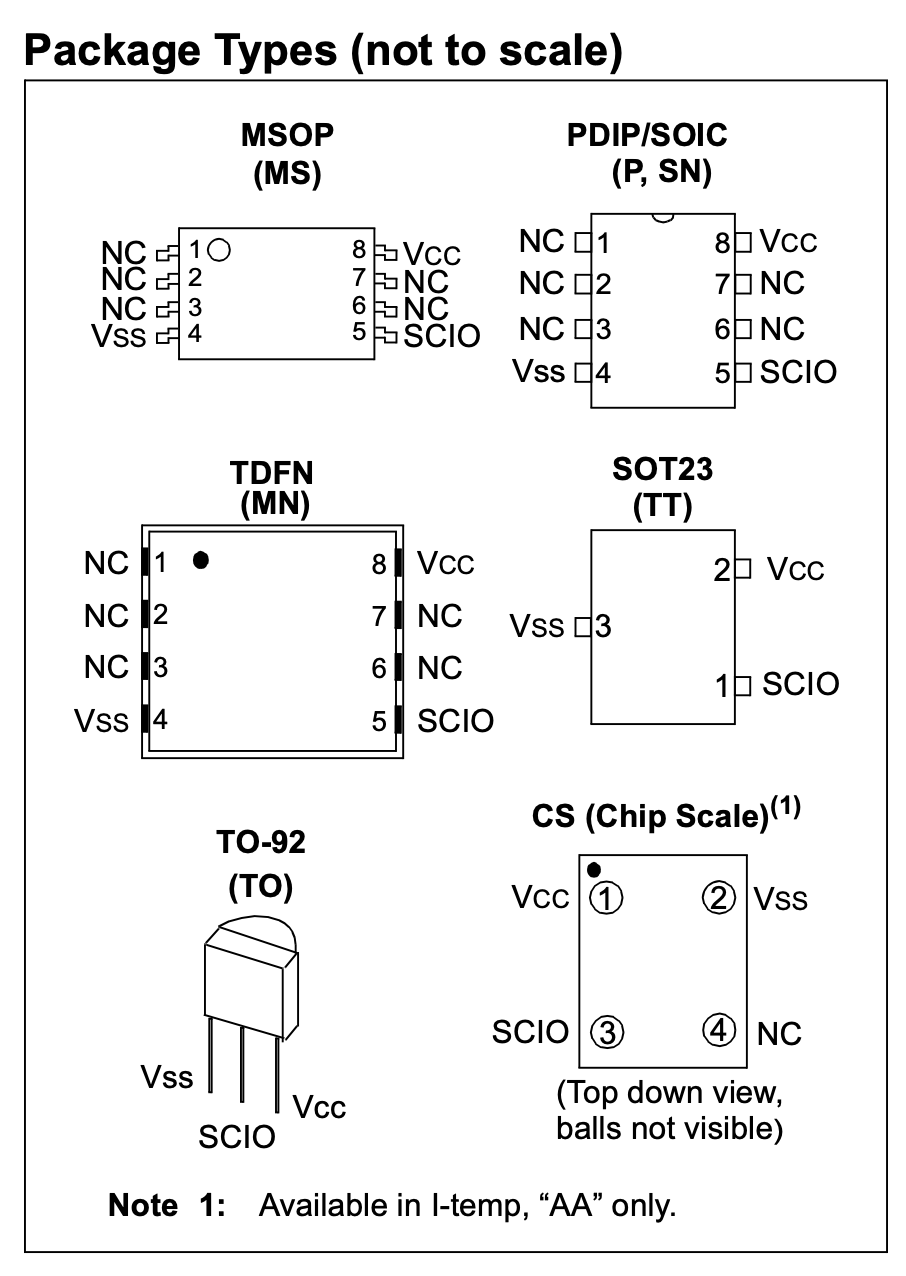
As the name says, the bus uses a single line to interface the chip.
SCIO:SerialClock, DataInput/Output
Continuing searching for the 11LC010 will at some point result in finding a very good source for creative solutions and hacks HACKADAY, which hopefully all players will already know. HACKADAY as an article from 2014 titled resetting DRM on 3D printer filament. As the article states, the chip used with the filament is exactle the challenges target chip. While the link to the voltivo website is dead, a bit of creative searching should bring the players to the applicable repo on github. The big question there is, how to connect the chip to the Arduino. Reading through the code one will find references to UNIO_PIN and the line #define UNIO_PIN 10. Thus pin 10 is needed.
Sadly pin namings aren’t always unambiguously, thus the pin 10 required from the code actually is pin D7 on Arduino Nano from the CTF. This can either be extracted from schematics or simply bruteforced, by trying a few of the pins.
Flashing and running the code from that repo will already solve the challenge.
Testing connection to Da Vinci EEPROM CHIP

Testing connection to Da Vinci EEPROM CHIP

Da Vinci EEPROM found...
Reading the Davinci EEPROM Contents...
(success)
00: 2E3A234E5E297D425A365D7B3B676468 .:#N^)}BZ6]{;gdh
10: 2D665936687C5A7E3E4E3E403E24645F -fY6h|Z~>N>@>$d_
20: 7A4A4F6D46347C6A434C7B2F3E4D2B55 zJOmF4|jCL{/>M+U
30: 496474755D237B6D29595268433D2472 Idtu]#{m)YRhC=$r
40: 38785B5E75615132557577717A5B5835 8x[^uaQ2Uuwqz[X5
50: 31724552392F702B256925757C34386A 1rER9/p+%i%u|48j
60: 4E73596626355048432B5A7270373932 NsYf&5PHC+Zrp792
70: 565A473531332B373931443F7B557200 VZG513+791D?{Ur.
(success)

Press enter to update EEPROM...
The flag can be found in the last two lines and is HC+Zrp792VZG513+791D.
H8: Single Wire EEPROM / 11LC010 TO-92
The single-wire EEPROM in the TO-92 package contains both a simple flag and a hint for H9. The challenge with H8 is the formatting of the content. All data is shifted by one nibble. Thus the sequence ABC or 41 42 43 looks like `04 14 24 30. As such the dump requires some manual analysis.
The EEPROM can be dumped just the same as the other 11LC010 was dumped in H7.
00000000: 0537 4617 2744 b657 93a4 6354 2323 3413  .7F.'D.W..cT##4.
00000010: 8463 1313 0304 5434 4443 4323 5613 1303  .c....T4DCC#V...
00000020: 9393 a456 e644 b657 96a2 75f4 4346 15e2  ...V.D.W..u.CF..
00000030: 47b4 9752 4267 74d6 d487 83a7 e704 e6b6  G..RBgt.........
00000040: 8483 22b6 5756 8333 6384 b475 3373 0332  ..".WV.3c..u3s.2
00000050: b353 1414 62e5 7773 c6f2 17c4 b793 d544  .S..b.ws.......D
00000060: 5676 d3c7 6576 1406 e514 d3b4 b363 e577  Vv..ev.......c.w
00000070: a455 2664 5494 6492 3322 9797 7353 54d0  .U&dT.d.3"..sST.
Looking through one will find the bytes 8483 22b6 5756 8333 6384 b475 3373 0332 b353 1414 62. Removing the first and the last nibble brings us to 483 22b6 5756 8333 6384 b475 3373 0332 b353 1414 6 and thus our flag H2+euh368KGS703+51AF.
If you haven’t played with data(structures) a lot, I can highly recommend giving CyberChef a try. You can simply delete the leading 8 and see the flag.
H9: NFC Dongle
The NFC dongle simply contains a flag and no further secrets. It can either be read using the correct key extracted from H8 or cracked using the various vulnerabilities in MiFare Classic cards.
S12: ESP32
The ESP32 is flashed with MicroPython and contains a simple text file containing a flag. The flag can be found when entering the interactive shell on the board.
Details will follow.
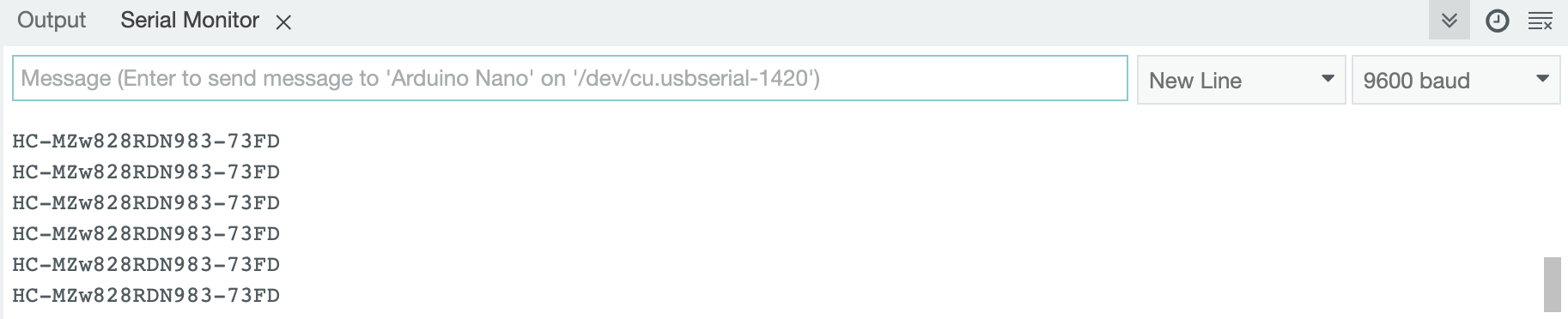
S1: Arduino Nano
The Arduino Nano exposes a flag via the UART interface directly after connecting it. The flag can be seen when using a tool like minicom or the Serial Monitor in Arduino IDE.
S2: Evidence Box
The evidence box has a sticker with a PDF 417 code containing a flag stuck to bottom of it.
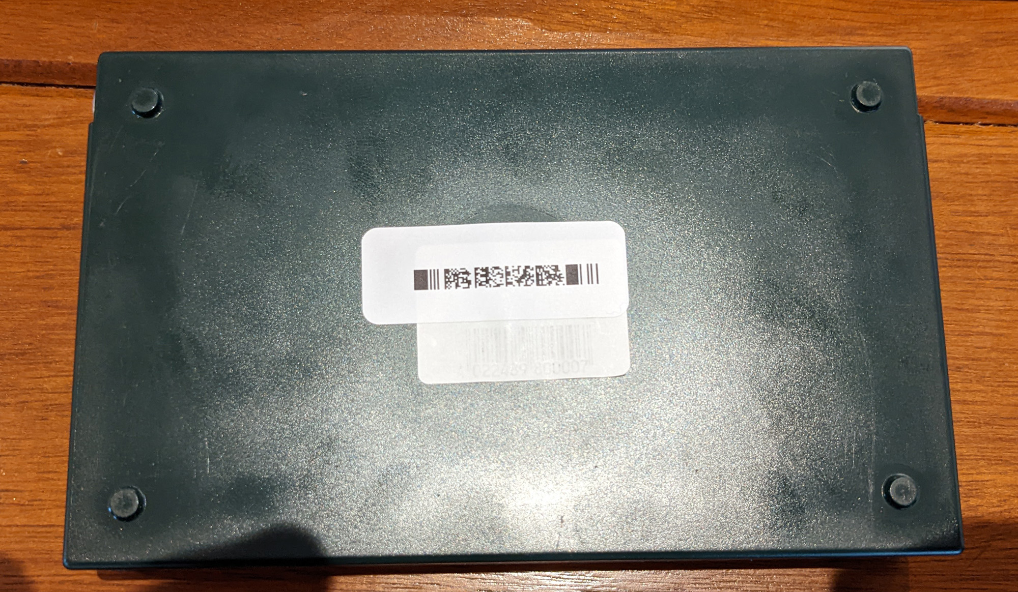
Most code reader apps on Android and iOS can be used to read the code.
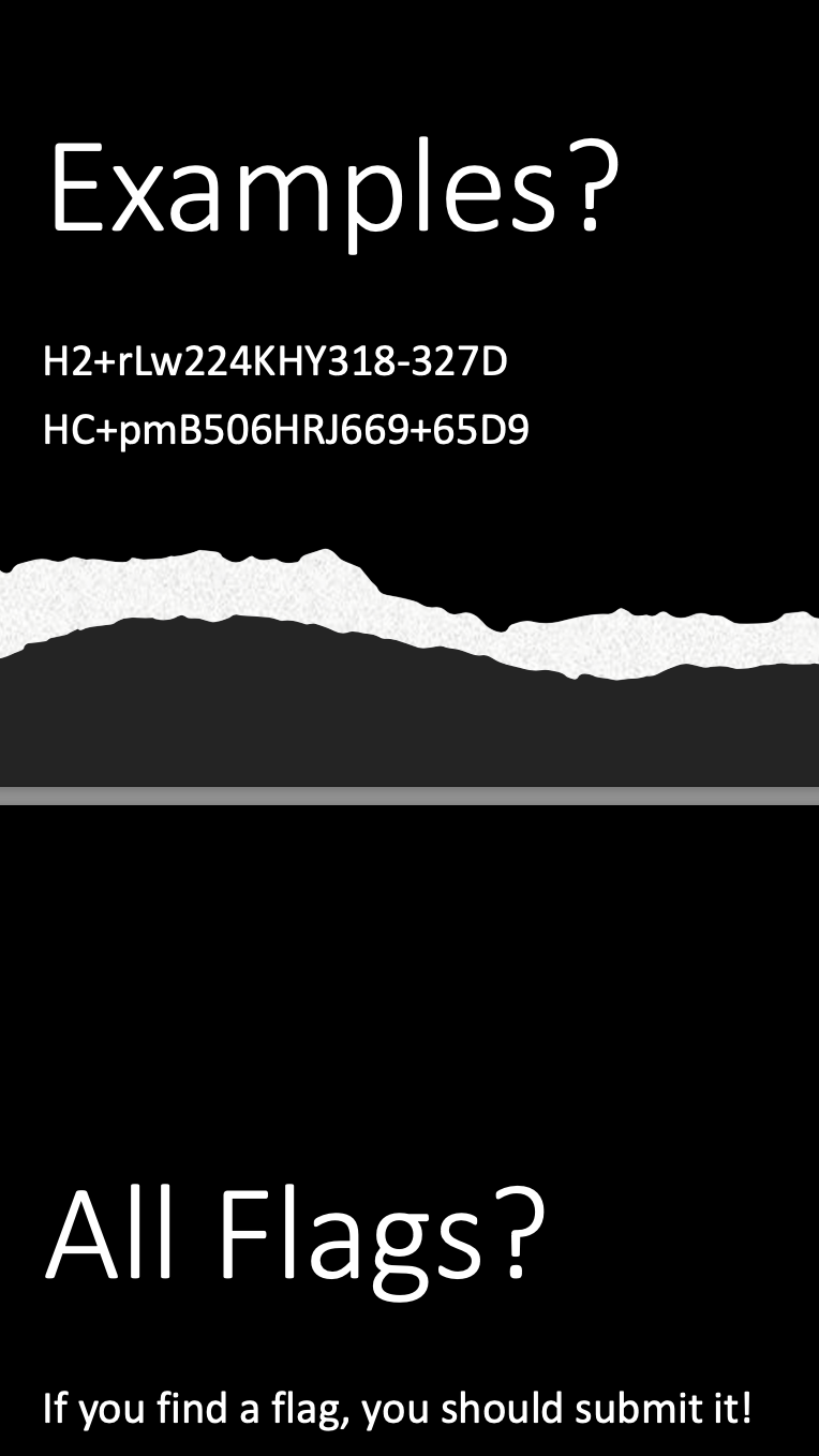
S3 & S4: Slides
The slides contain 2 valid, exemplary flags, which could have been submitted.
Day 2: The Envelope
On day 2 the players receive an envelope with a few bits:
- Scoring sheets: Pre-printed paper to submit the flags
- A single NTAG215 NFC Tag
- A USB Stick
- A SIM Card
- The business card of Pastor Manul Laphroaig
Crimescene Images
The crimescene images reassemble a challenge concerning proper documentation. The players have to check the images, use the hints were possible and note the number of the picture, the piece of evidence it relates to and which flag could be extracted from the image.
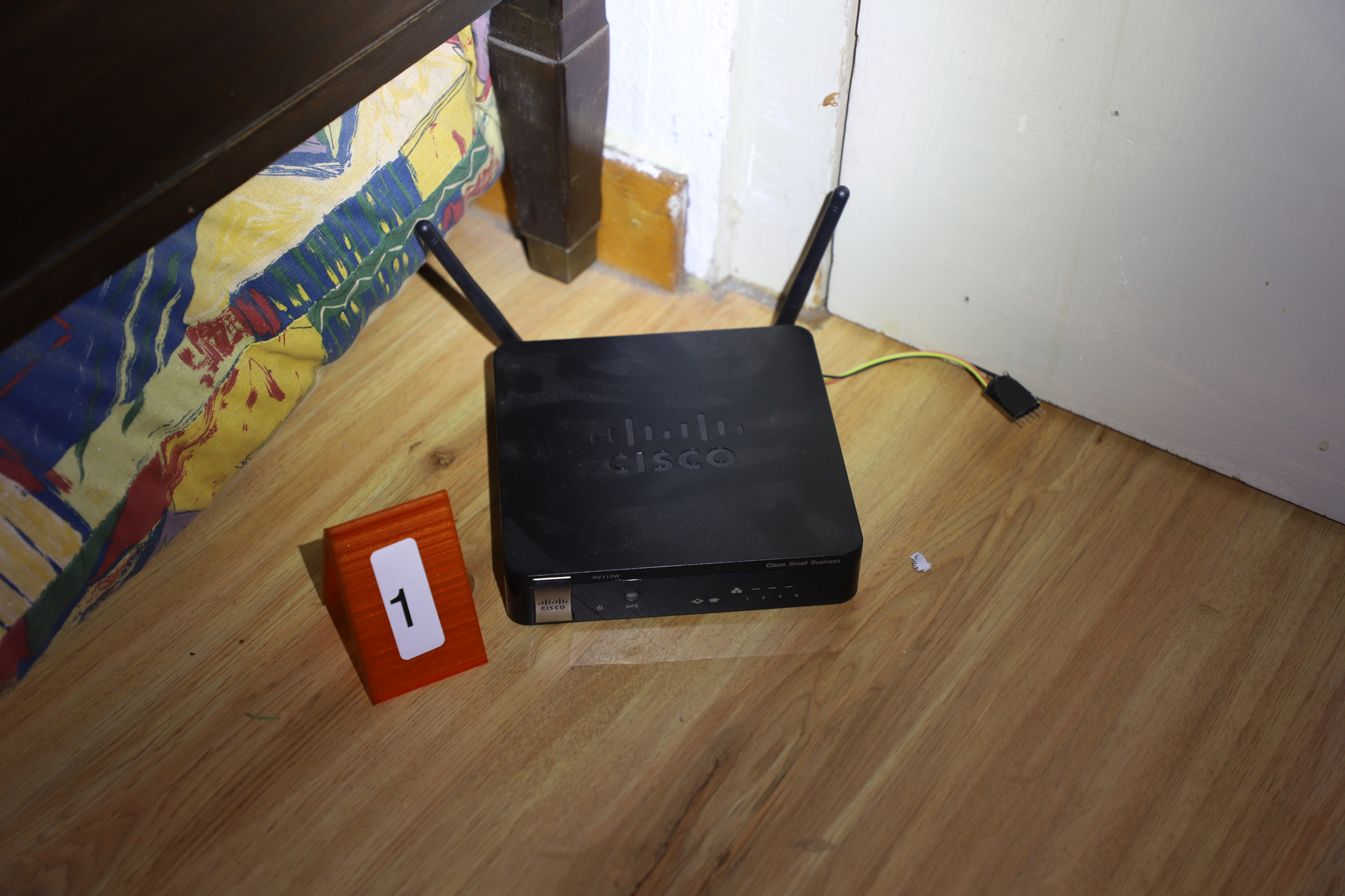
E1: Picture 1
Picture 1 shows a Cisco RV110W which has a few known vulnerabilites. The related object is the I2C Memory Chip (H1). The image starts with the String CISCO and thus refers to the router.
E2: Picture 2
Picture 2 shows 5 NFC cards and a sequence of letters on a piece of paper next to them. The letters are the beginnings of each of the colours and thus give the order.
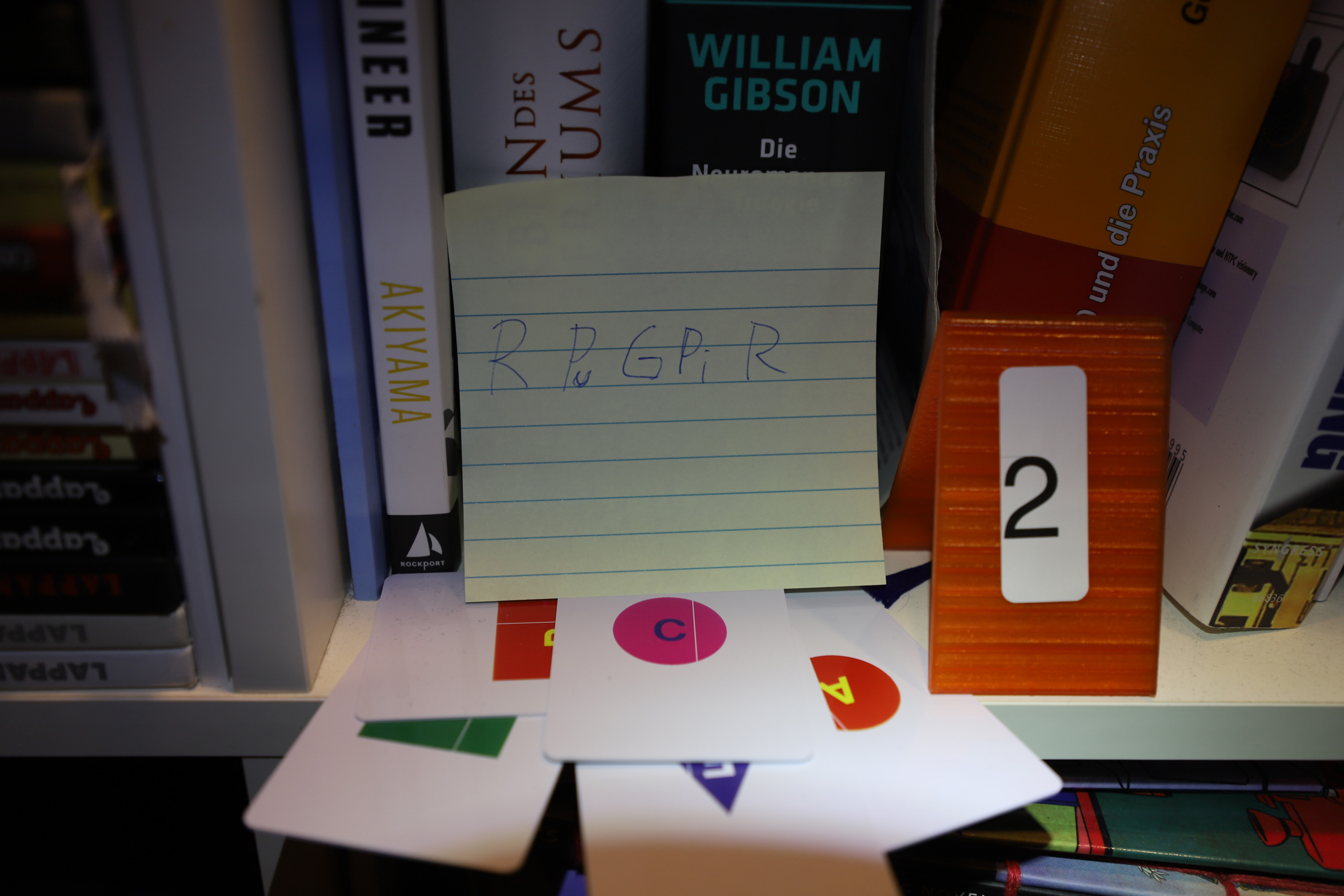
The cards needed to solve this puzzle are the green square, red square, red circle, pink circle and purple triangle. The note says R Pu G Pi R and as such Red, Purple, Green, Pink and Red. Having two red cards the order as to be derived from the content and the knowledge about the flag format. Thus the first Red has to contain either H2 or HC.
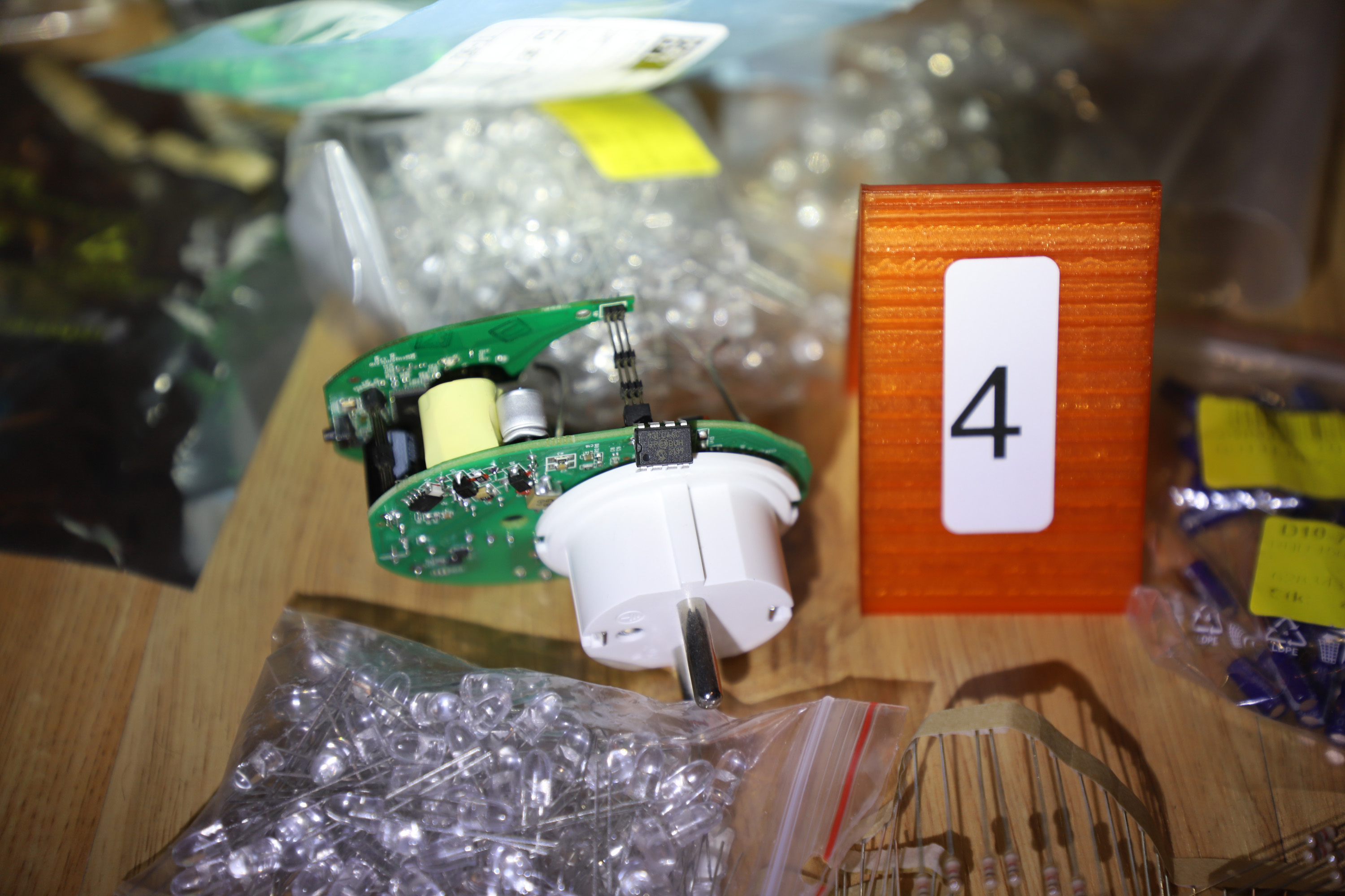
E4: Picture 4
Picture 4 shows a bunch of smart powersockets by “Smart Inc”.
E5: Picture 5
Picture 5 shows 5 NFC cards and a series of symbols on a notepad. The symbols give the correct order of the cards.
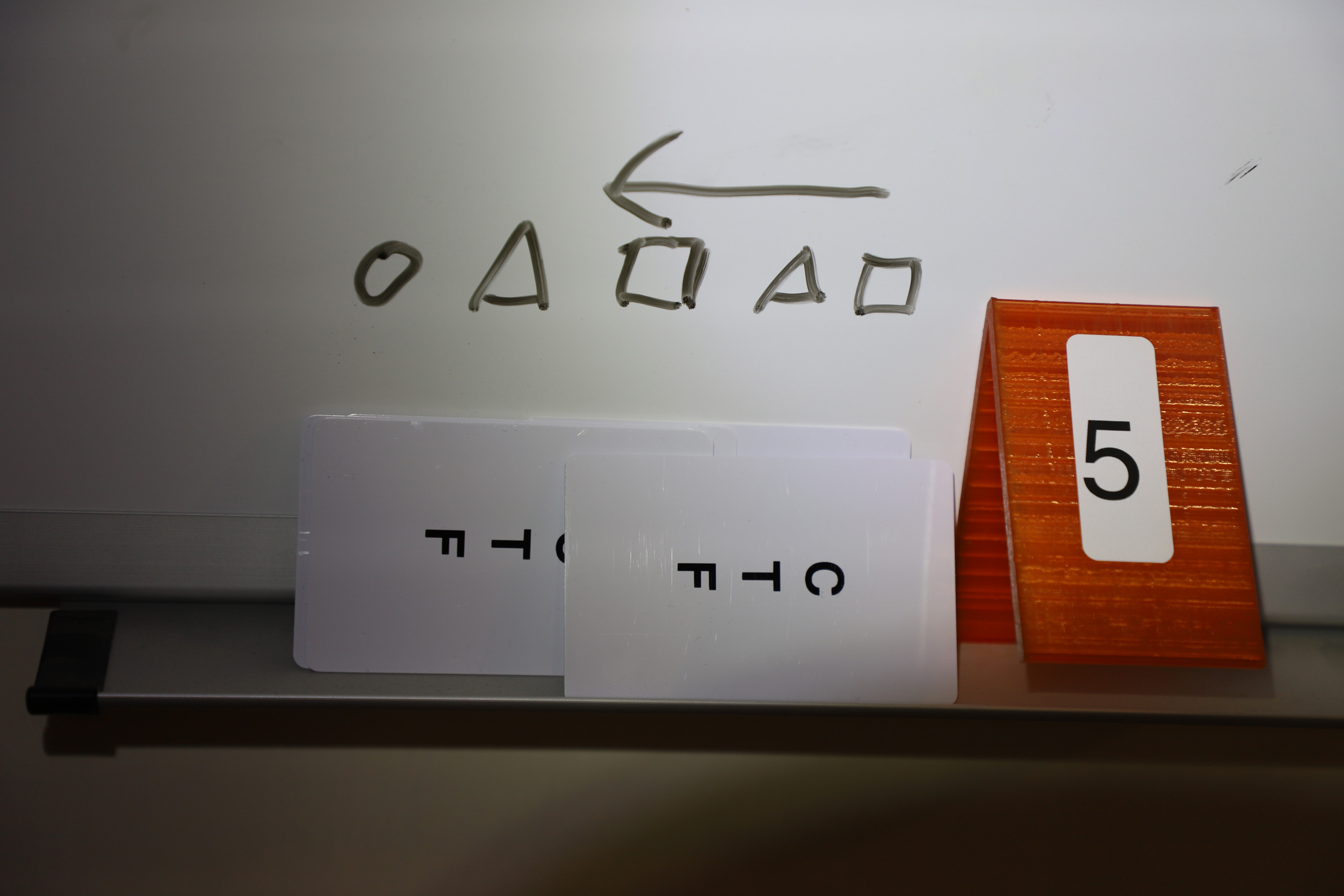
In contrast to E2 the picture does not show which cards are necessary for the challenge. With there being 10 cards and five having been used in E2, the other 5 have to be used for E2.
The board shows 5 symbols, a circle, a triangle, a square, a triangle and a last square. The arrow above the symbols gives the hint to read the order from the back. Thus square, triangle, square, triangle, circle is the correct order. There yet again is a double symbol, the square. Looking at the flag format, it becomes clear that the third card from the back has to contain either a + or -.
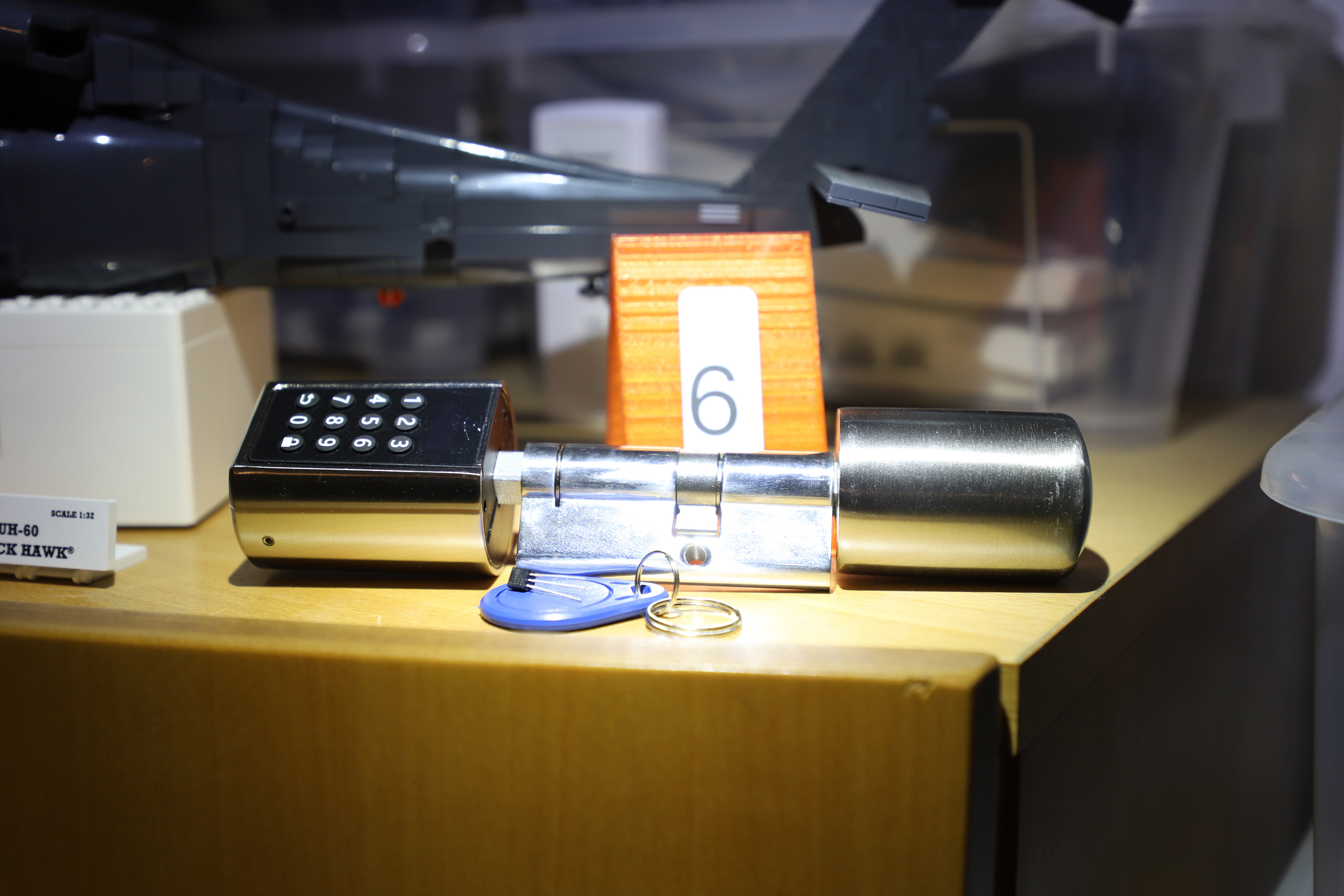
E6: Picture 6
Picture 5 shows a smart lock, an NFC dongle and the TO-92 single-wire memory chip. The chip contains both a flag and the keys to access the dongle.
E7: Picture 7
Picture 7 shows an old mobile phone and four dice which reassemble the SIM PIN.
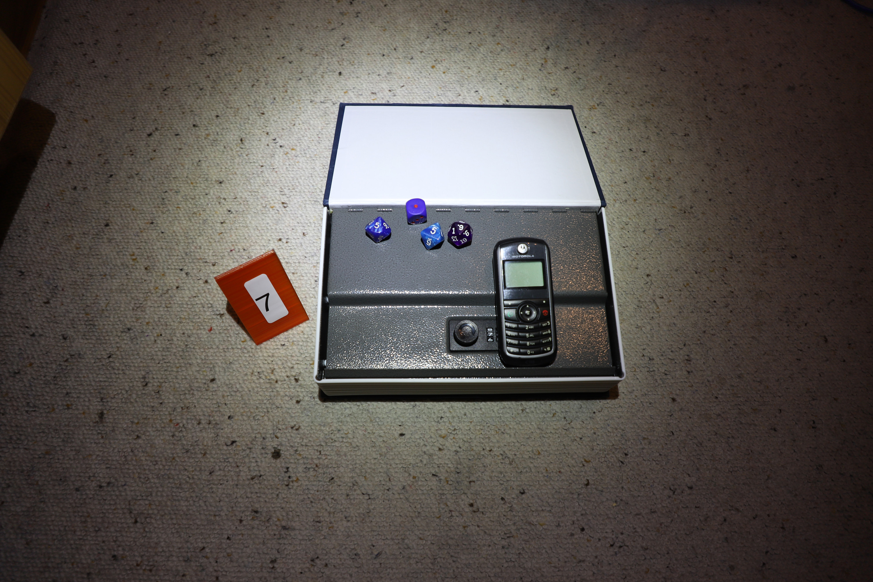
E7 contains a little bit of a trap. While at first sight the last dice looks like a 9, there is a small decimal point showings its actually a 6.
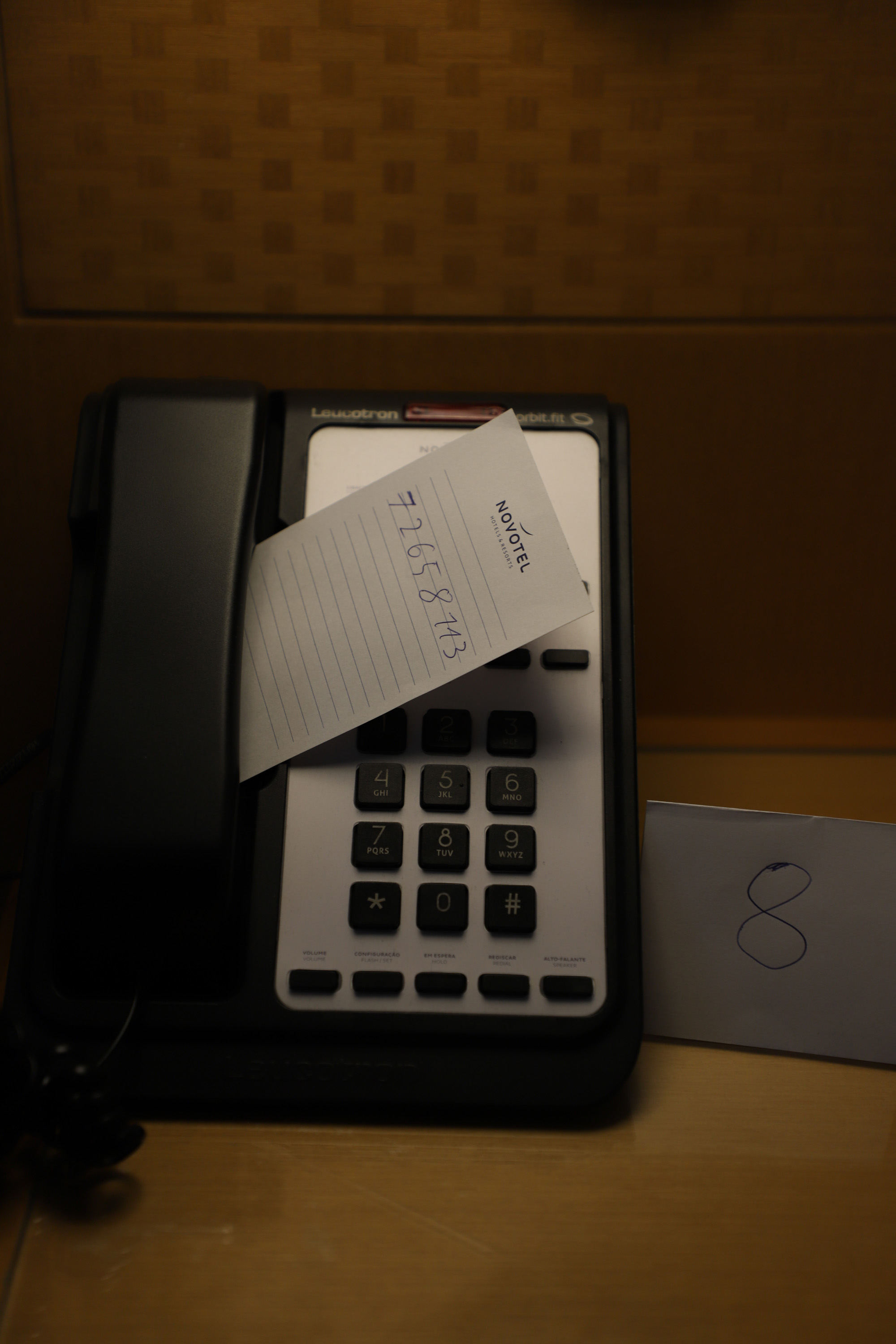
E8: Picture 8
Picture 8 shows a phone with a notepad with a number next to it. If you call the number with the SIM, a voice will dictate a token.
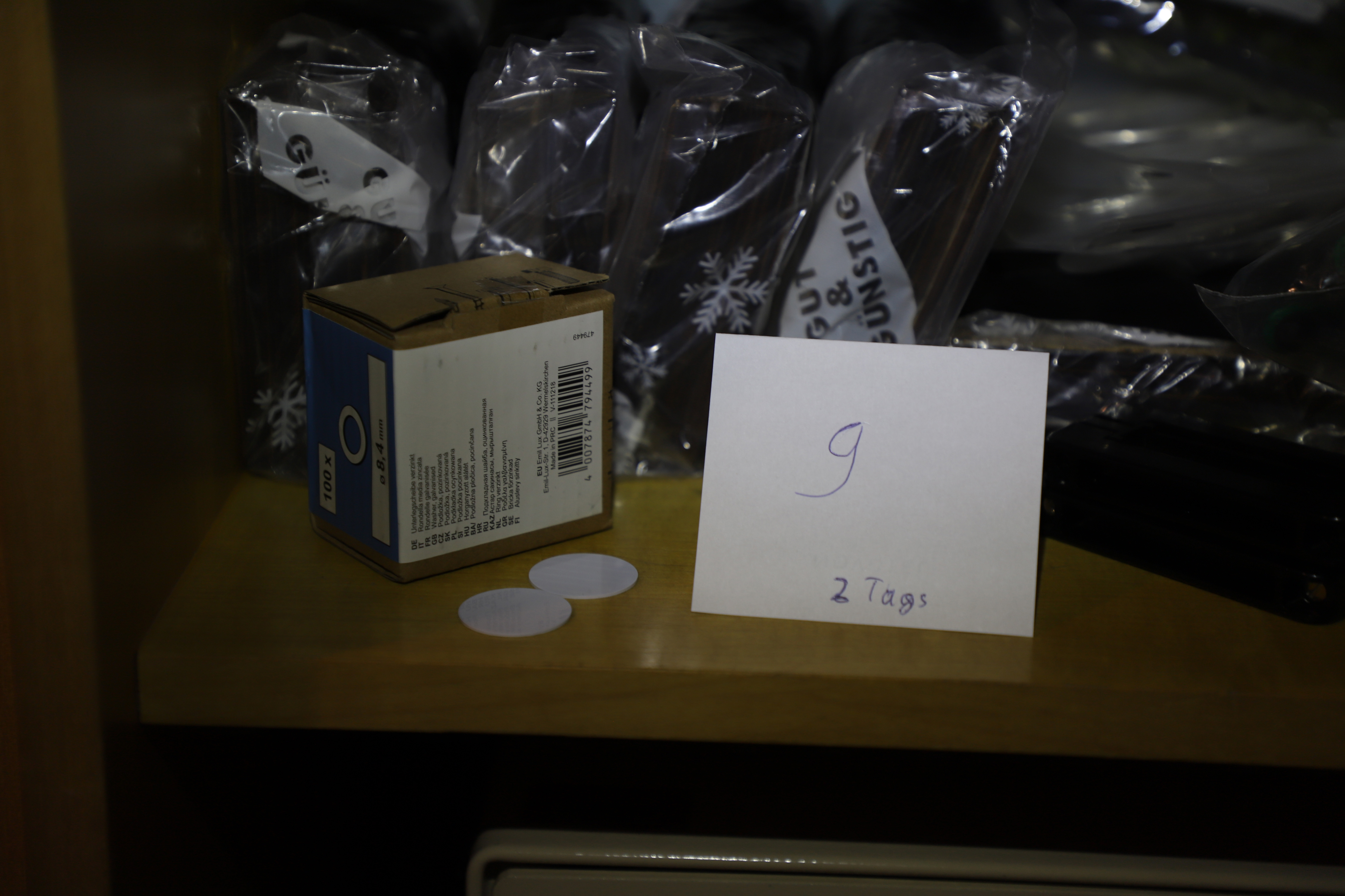
E9: Picture 9
Picture 9 shows two NFC tags, which is also stated on the crimescene tag. During the game the players only received one single NFC tag in the day 2 envelope. The missing tag could have been picked up by the players at any time, by asking. As such the challenge here was reading and a proper recon phase, during which the missing tag would / could / should have been noticed.
Correct Submission
As described before, the players had the chance to bring the identified flags and evidence into context. This is what a correct submission would look like.
| # | Evidence | Flag | Why? |
|---|---|---|---|
| 1 | 24LC01B-I/P | HC+KJW373YGX105-FAE8 | The string “CISCO” in the memory refers to the router |
| 2 | NFC Cards | H2+Jac718LNK726+87BF | The cards are on the picture |
| 3 | - | - | Evidence 3 does not exist |
| 4 | |||
| 5 | NFC Cards | H2+Jac718LNK726+87BF | Only scores once |
| 6 | 11LC010 (TO-92) | H2+euh368KGS703+51AF | EEPROM can be seen on the picture |
| 7 | SIM Card | HC-xYF351ANZ977-3D0A | The mobile phone should be a hint for the SIM, also the dice show the SIM PIN |
| 8 | - | - | Decoy, gets the players Rick Rolled |
| 9 | NFC tag | H2-ixS256EFW343-30CC | The tag is on the picture |
The lines 3 and 8 are only listed for completeness, also either line 2 or 5 could have been omitted, and could have been used in case of a draw.
USB Stick
U1: file1.bin
file1.bin contains a typical combination of a Flag character and the address for the next character. The special aspect is the file only contains one single H which is a flag’s starting character. Thus having found the H the players can continue to the next character and so on.
The raw dataset looks something like this
{3715: ('H', 362), 362: ('2', 4662), 4662: ('-', 4899), 4899: ('K', 3560),
3560: ('L', 3190), 3190: ('N', 1340), 1340: ('7', 4857), 4857: ('6', 3421),
3421: ('0', 4576), 4576: ('Y', 4277), 4277: ('P', 2036), 2036: ('U', 23),
23: ('8', 1392), 1392: ('2', 639), 639: ('2', 381), 381: ('-', 2847),
2847: ('0', 3655), 3655: ('x', 4703), 4703: ('f', 211), 211: ('b', 3071),
3071: ('7', 1233), 1233: ('c', 65535)}
Just containing a bunch of seemingly random binary data, the players were expected to open the file with their favourite hex editor and start hunting for a flag. While HC and H2 won’t help, the file only contains a single H.
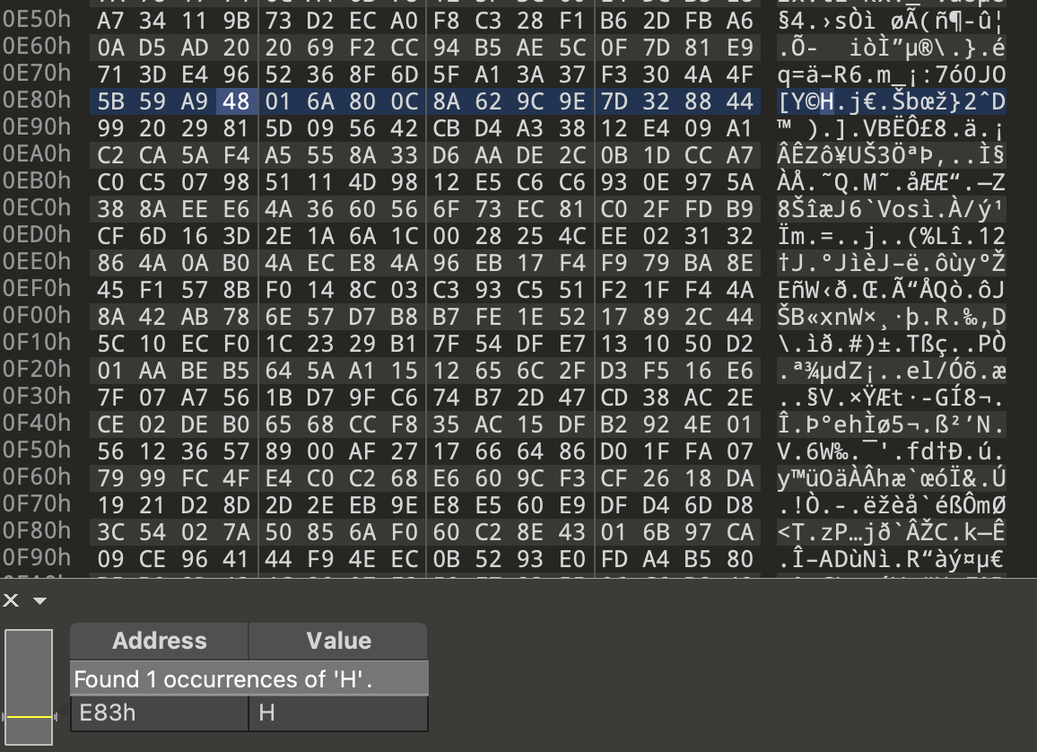
The H is followed by the bytes 01 64 where we can find a 2.

The 2 is followed by the bytes 12 36 where we can find a -.

And so on…
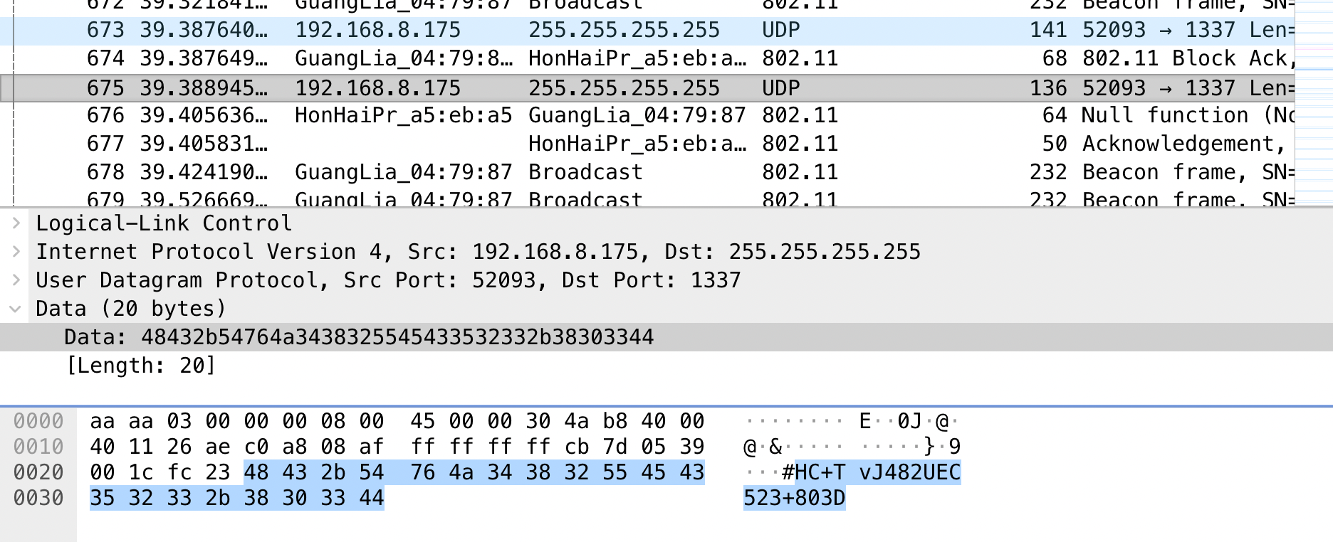
U2: sniff.pcapng
sniff.pcapng contains an WPA2 encrypted WiFi sniff for the SSID “Laika”. The password is extracted from E1. It eventually contains a simple flag broadcasted via UDP.
When initially opening the file in Wireshark the players will see the sniff of an encrypted WiFi network and thus not much interesting, except for a hint for S10, the WiFi name Laika. But in combination with H1, where the String PW: Mn58Jdfq4! can be found, the players can decrypt the WiFi traffic.
Wireshark includes an option to directly encrypt WiFi sniffs, if both the PSK/PWD and initial handshake are in the sniff.
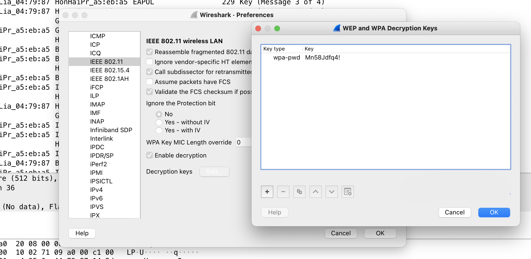
The flag can then be directly extracted from Wireshark.
U3: oob.pcap
oob.pcap contains a binary data transmission hidden as binary ASCII in the timings of the requests to https://h2hc.com.br or rather 178.79.131.56. A pause of 1-3 seconds is a 0, a pause of 7-9 seconds is a 1.
Looking at the sniff, the players won’t find any usable information in the file. The only parameter that can be found within the file is the timing / time different between the single packets.
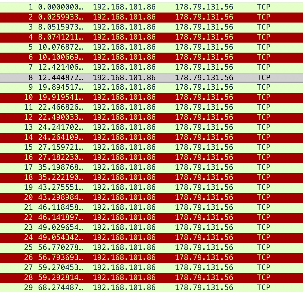
The first packet opens the file followed by a long pause, thus a 1. Extracting the binary stream, it reassembles the decimal representation of the characters of the flag H2-EII902NMN947-1D37.
U4: colours.xlsx
colours.xlsx contains a few coloured spreadsheet fields. Each column contains a sequence which in return shows a number as encoded on resistors. The number then directly relates to the ASCII code for a flag.
The challenge looks as follows.
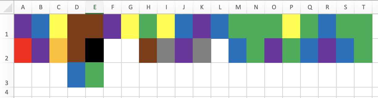
Having used and seen resistors and their values in the previous hardware challenges and tutorials, the players can recognize the colour codings / patterns. As such, to solve the challenge, they need a colour table like the one from Wikipedia.
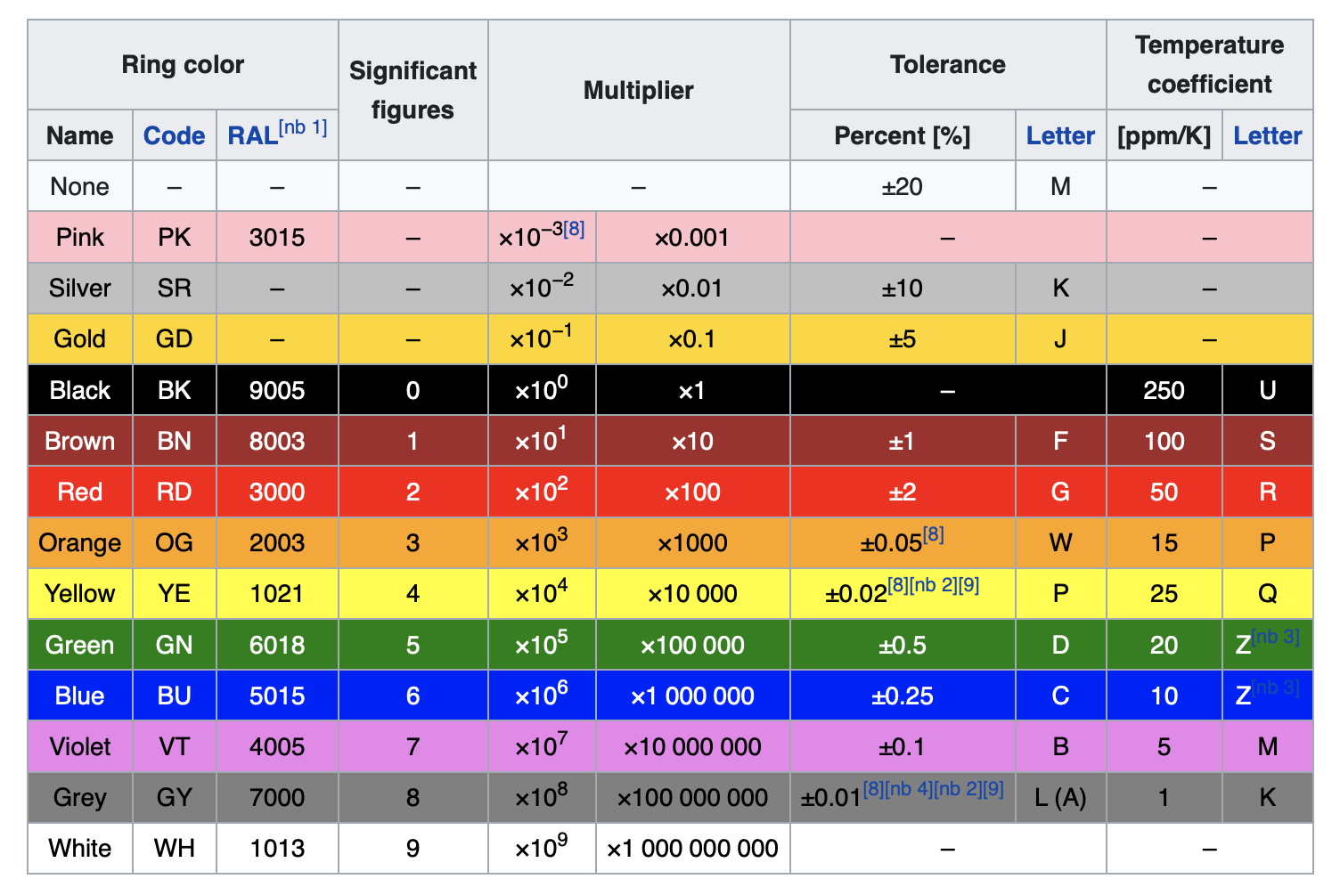
The solution then looks like this, and yes, the white spaces can be a bit tricky.
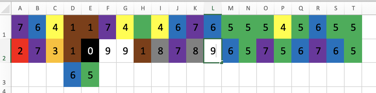
Starting with the first number 72 and knowing it has to be an H the players should recognize the data as being letters as decimal numbers. Then, for example using CyberChef again, the players can quickly decode the flag as being HC+tiO130CNE879-8C87.
U5: block.stl
block.stl is a simple STL - stereolithography - file format and used in 3D modeling and 3D printing. It’s simply intended as maybe being a new file format. It contains a flag as 3D modelled text in a 3D block which just has to be shifted.
The challenge is a bit of a simple tease and can be solved directly by opening the file in an applicable viewer of ones choice.


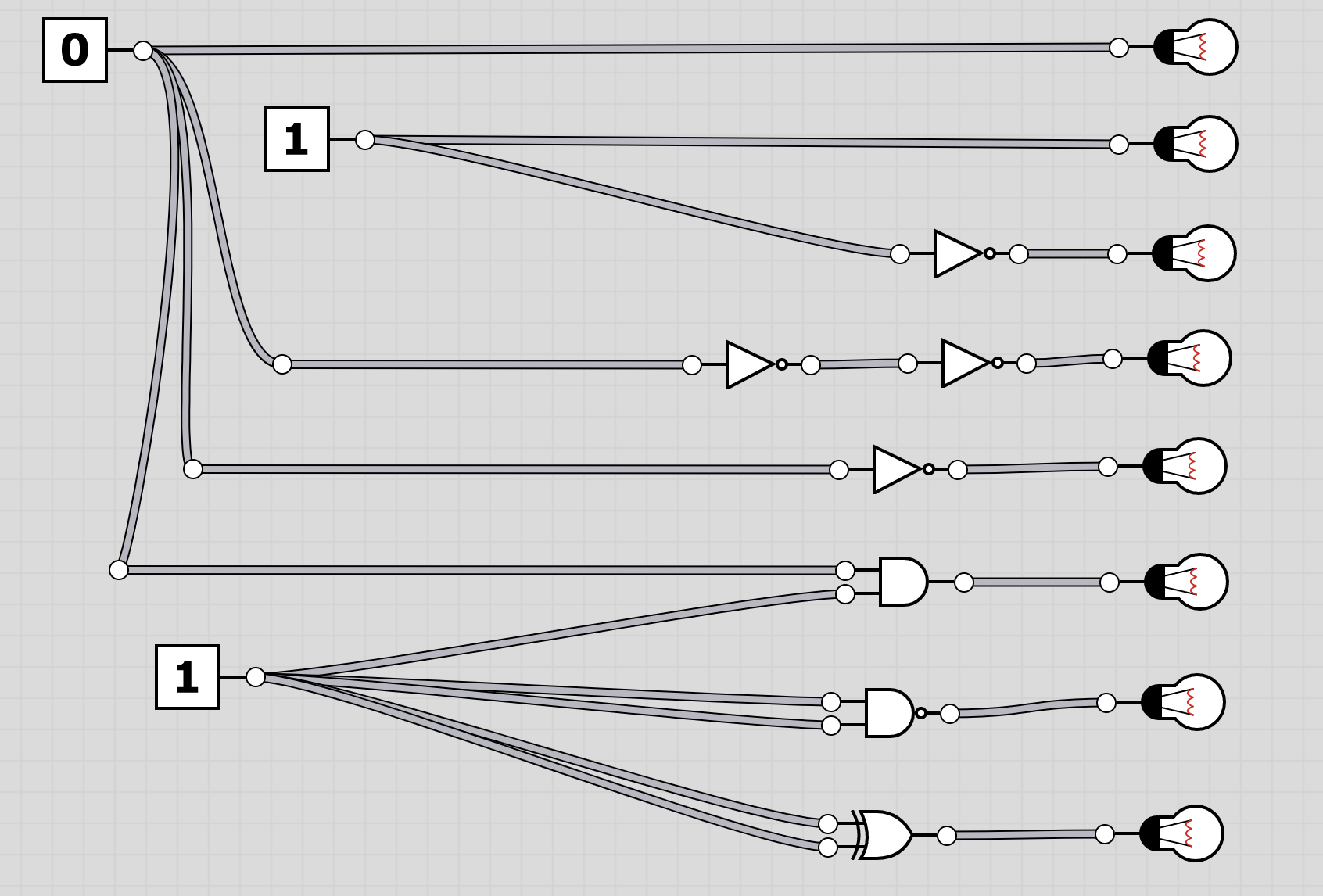
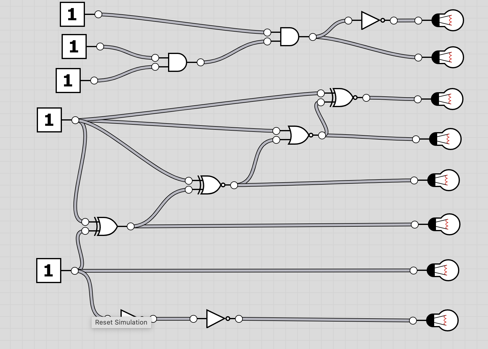
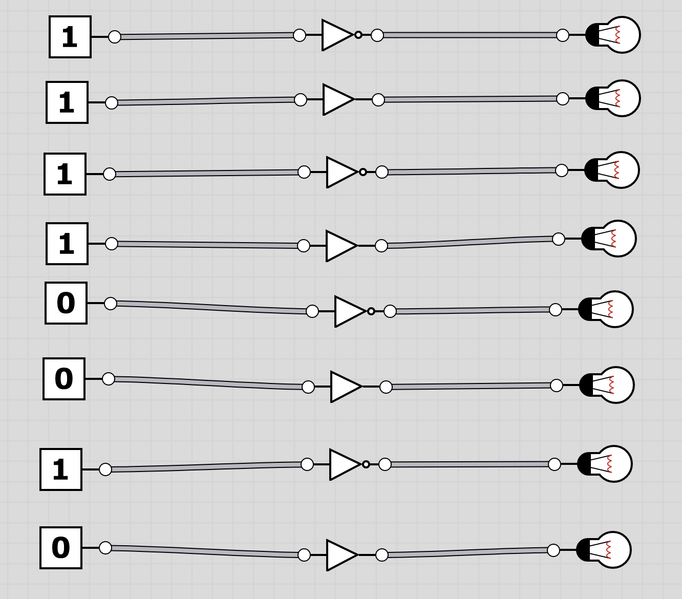
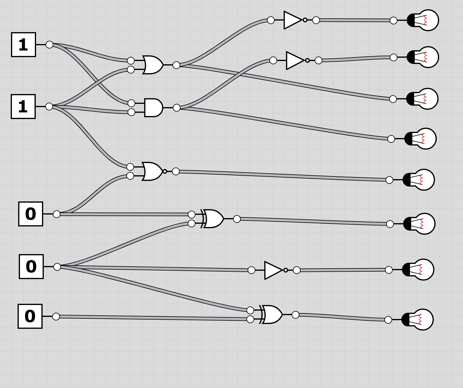
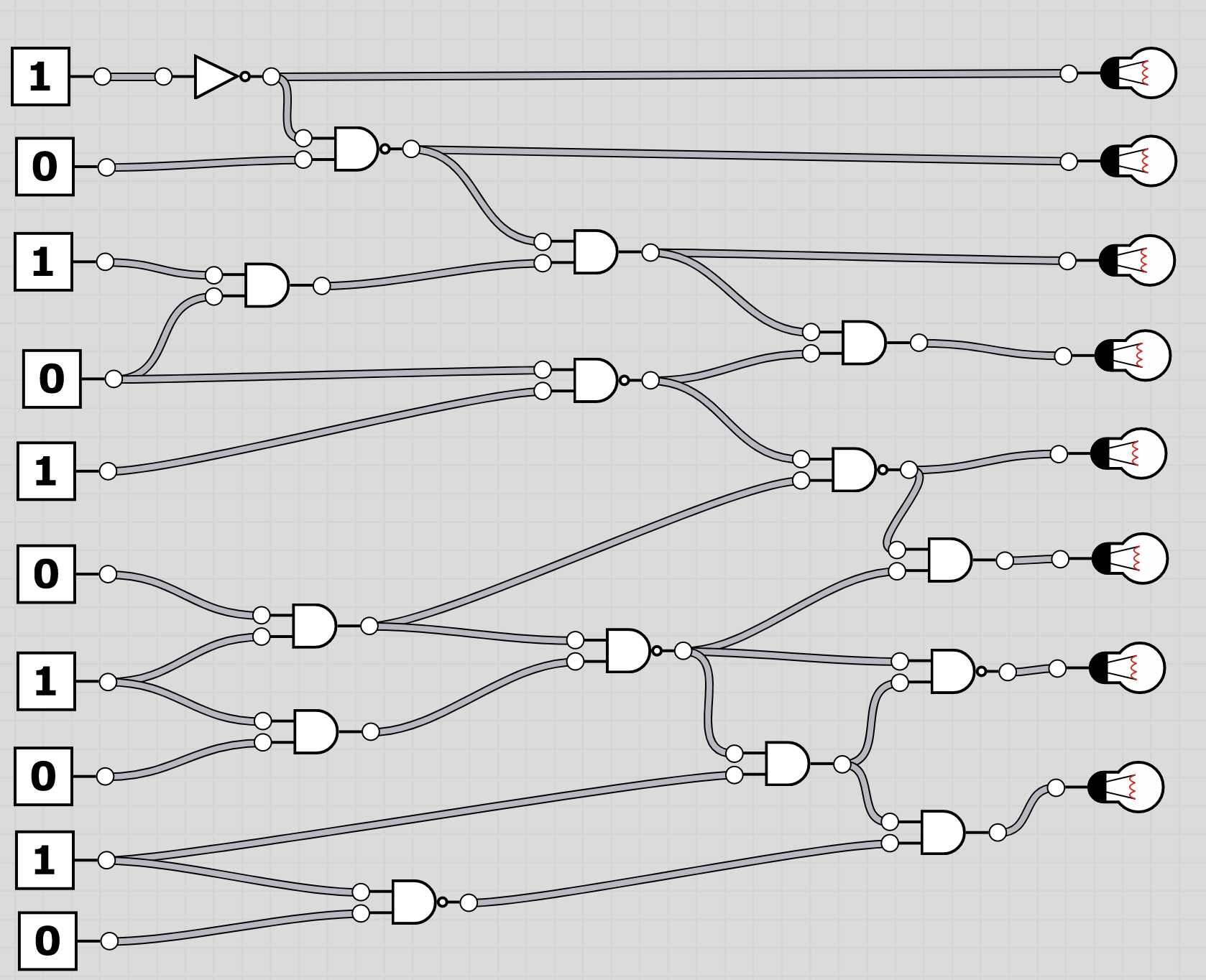
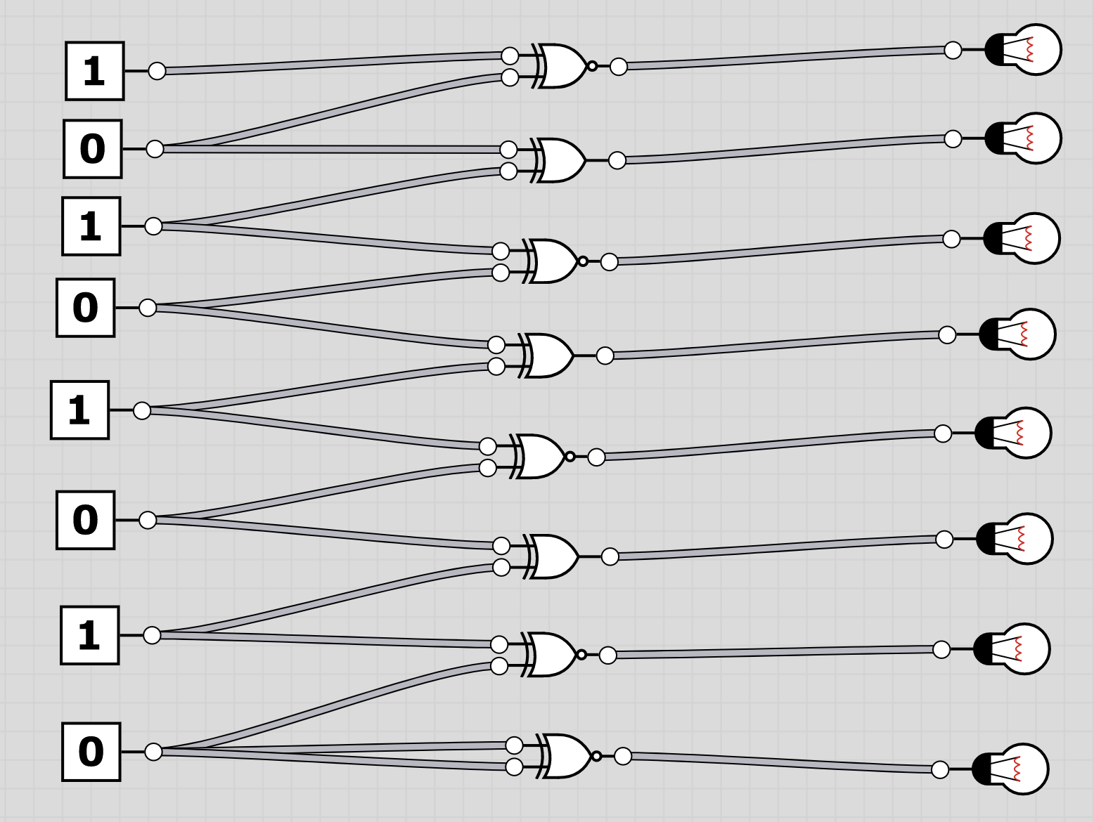
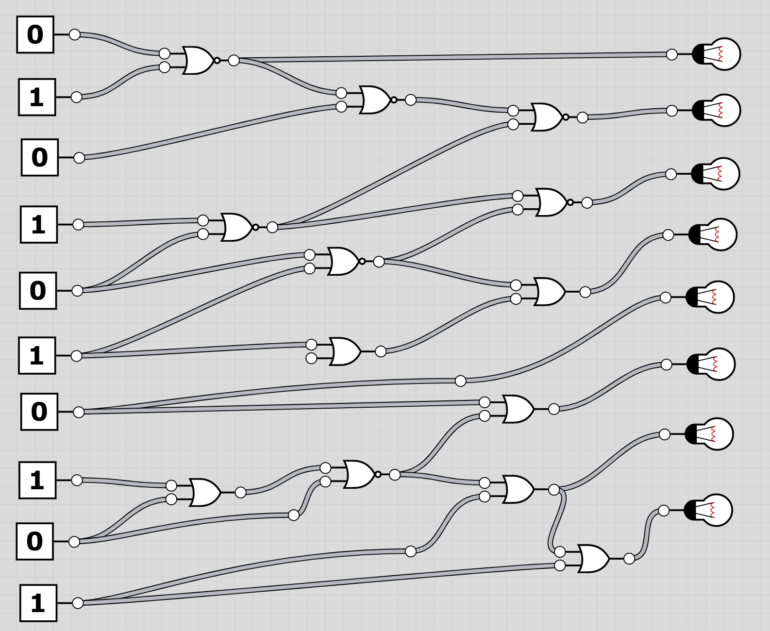
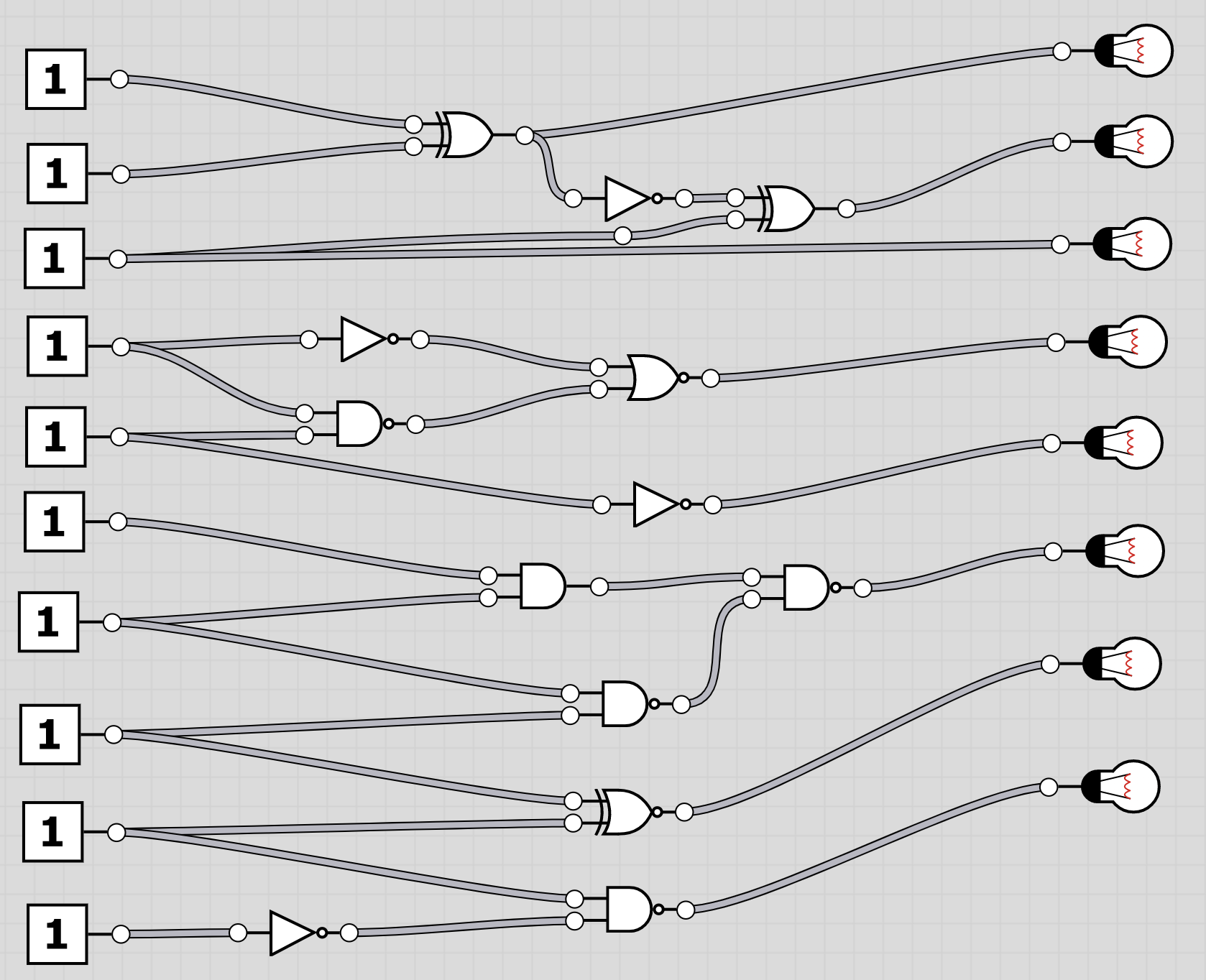
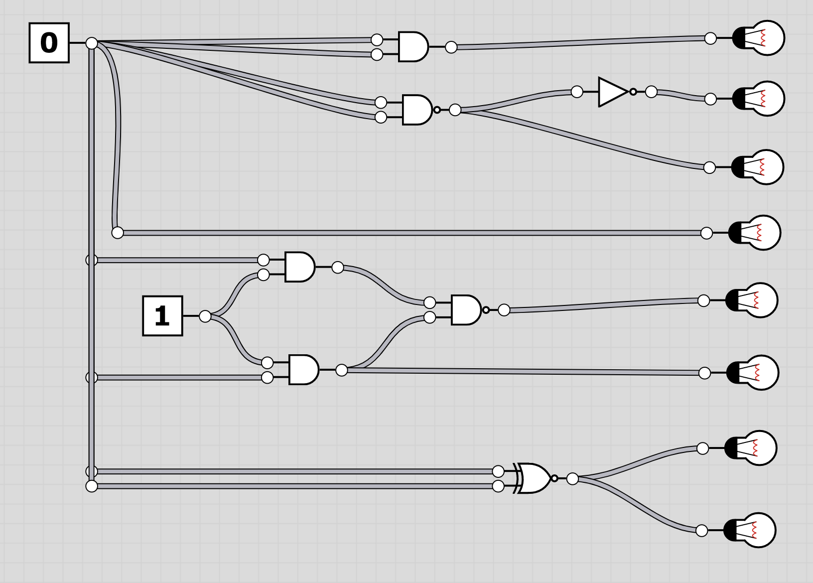
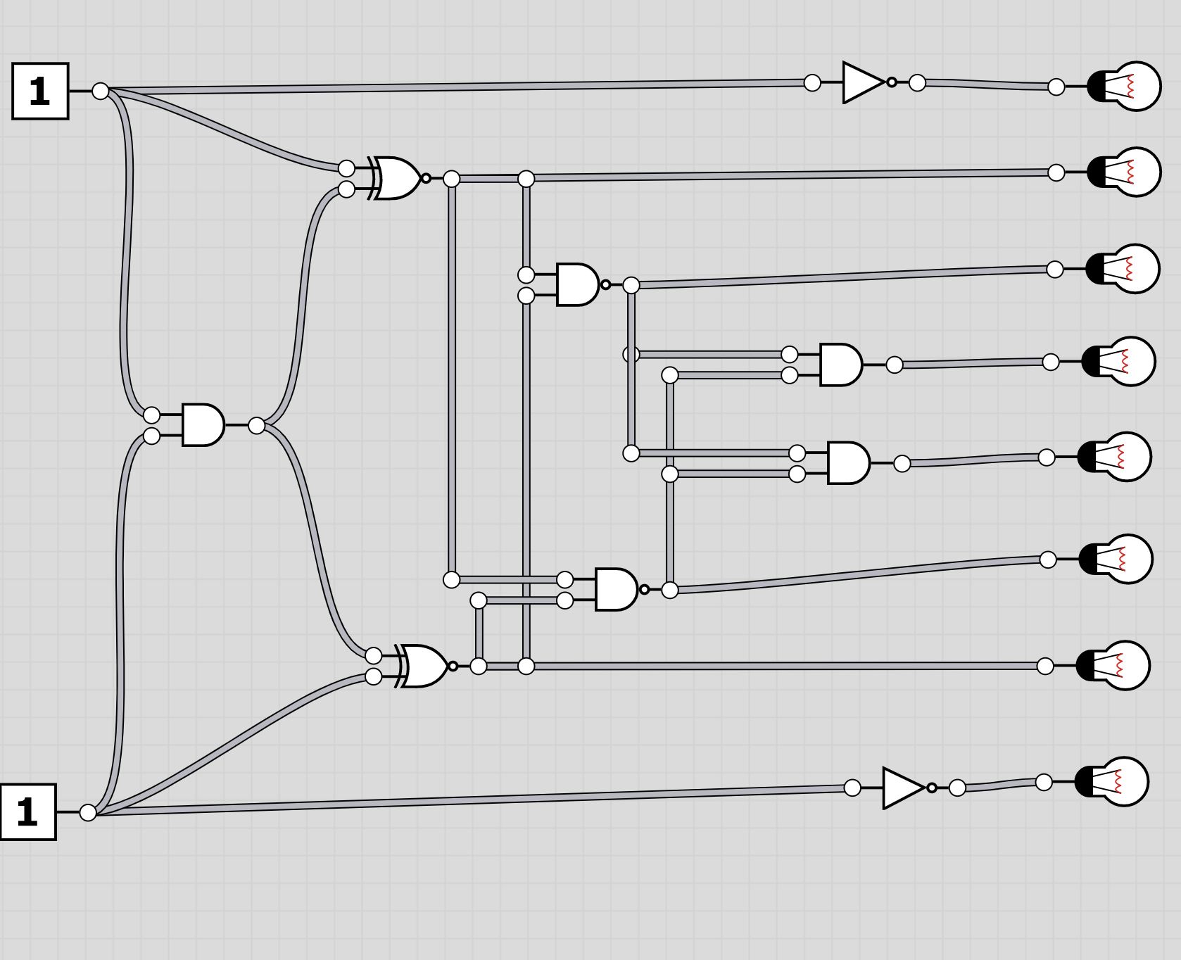
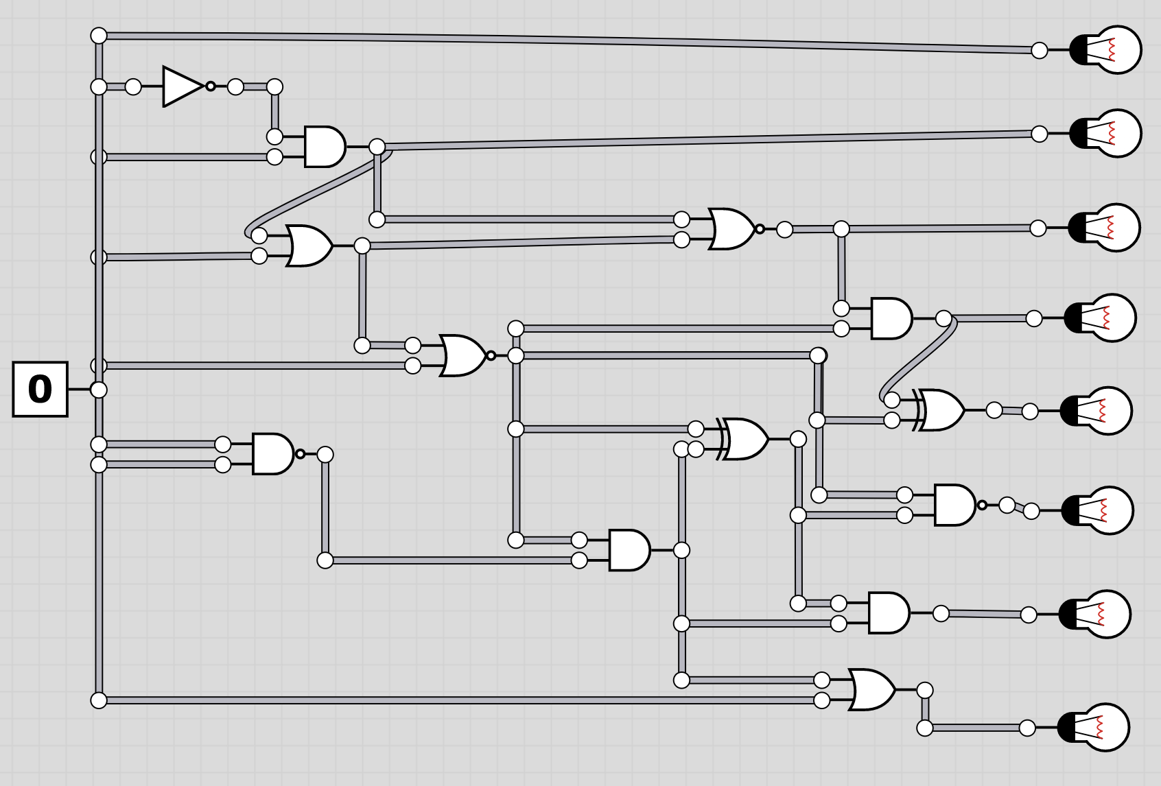
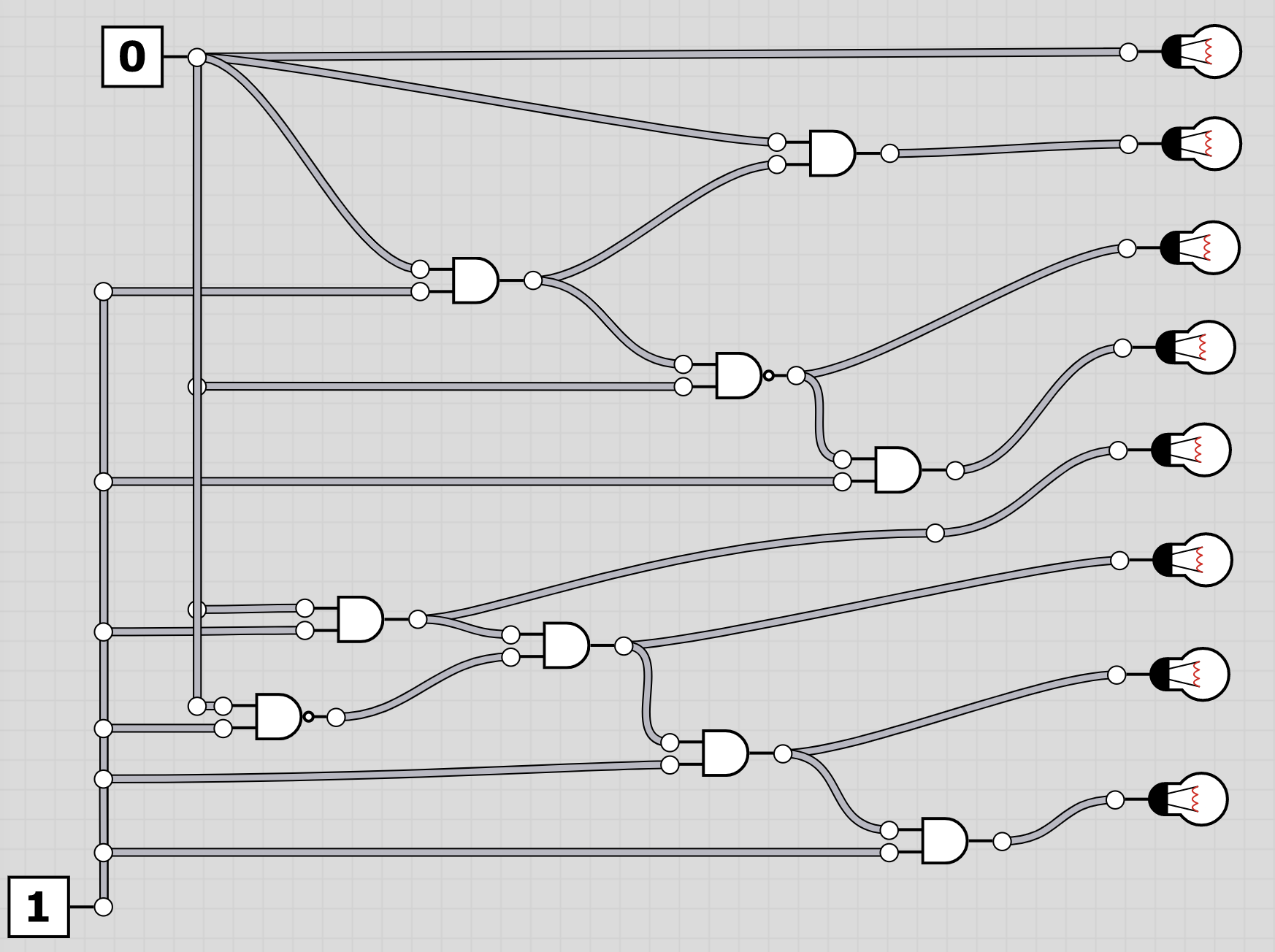
U6: logic
The folder logic contains 20 screenshots of logic circuits. Each image resembles the 8 bit of one of the characters of the flag.
| 1 | 2 |
 |
 |
| 3 | 4 |
 |
 |
| 5 | 6 |
 |
 |
| 7 | 8 |
 |
 |
| 9 | 10 |
 |
 |
| 11 | 12 |
 |
 |
| 13 | 14 |
 |
 |
| 15 | 16 |
 |
 |
| 17 | 18 |
 |
 |
| 19 | 20 |
 |
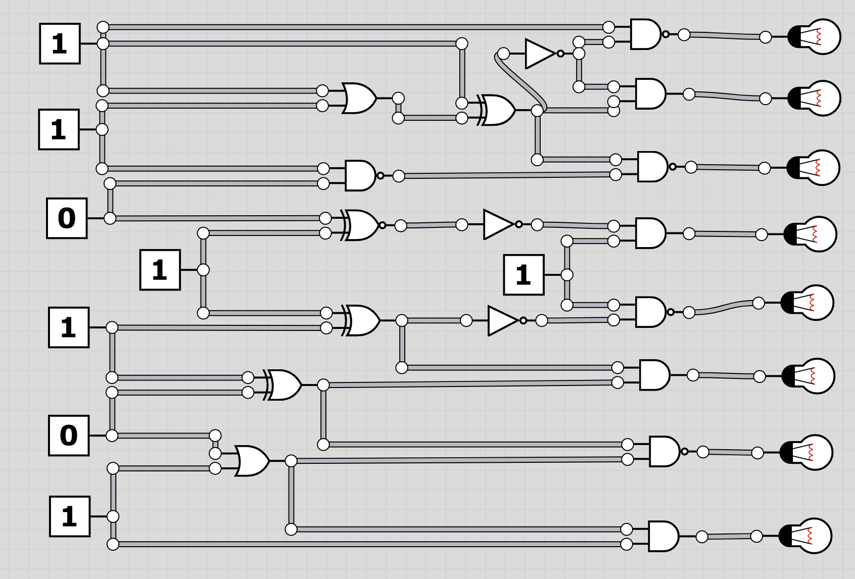 |
To extract the flag, the players have to follow through the logic gates and work out the state of the bulb at the end. Thus receiving the binary value for a character of the flag. Having solved all, the players should receive HC+XUY027MUU377+B501 as the final flag.
U7: flag.txt
flag.txt contains a flag with four characters missing. This is a little bit of a bruteforcing challenge. Due to having the CRC16 Checksum, the four characters can be recovered. Actually the H
to start with is even trivial.
The challenge looks as follows:
xC-vsu9xxOUA781x01CB
It can be trivially seen, that the flag is invalid, as not even the first character is correct. Knowing the flag’s structure, the players have to bruteforce the missing characters in the flag. Copied from above, the players know:
* H2 or HC
* 1 opening symbol + or -
* 3 letters
* 3 digits
* 3 capital letters
* 3 digits
* 1 closing symbol + or -
* CRC16 in 4 capital letters and digits
Thus the first x has to be an H, the next two have to be two digits, and the last x hast to be either a +or a -. Also the CRC16 checksum has to be correct.
The first challenge lies in understanding how exactly the CRC16 checksum is calculated. For this some reading, research and trying is necessary. The correct checksum is calculated using Pythons crc16` library:
import crc16
...
cs = crc16.crc16xmodem(flag.encode('utf-8'))
As such understanding the encoding is the biggest challenge. Afterwards a simple loop can be used to check all 10 * 10 * 2, 200 options for the correct flag. Eventually the player will calculate the flag HC-vsu978OUA781+01CB.
S5: USB Stick
Each USB Stick contains a small piece of paper with a flag on it.
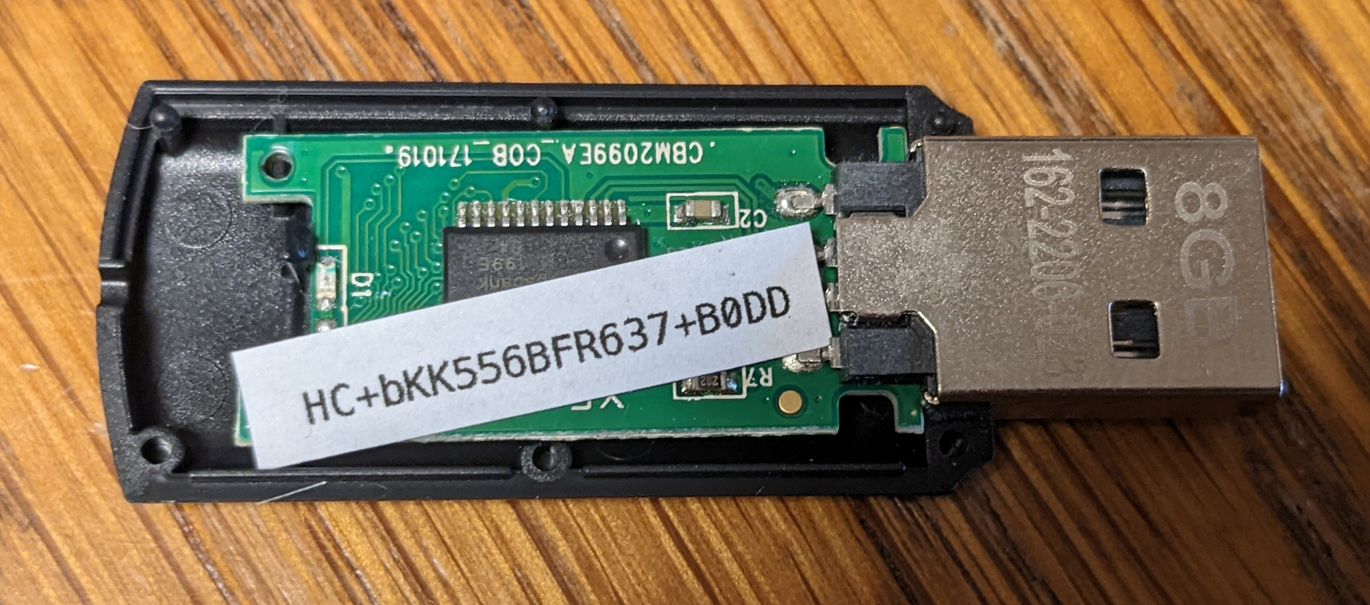
To find the flag the USB stick had to carefully been opened.
Admittingly, there was probably only a tiny chance of anybody actually finding it. That being said, a lot of people I hack and play with, including myself, bring so much courisity into the game, they would have tried to open the stick! Thus, I hope this write up motivates the readers to think out of the box even more!
S6: Business Card
The business card of Pastor Manul Laphroaig is a friendly reminder to all players, to have a look at the International Journal of PoC||GTFO. The QR-Code is a direct link to one of the mirrors. When calling the number, the players will hear a voice, similar to the one of late physicist Stephen Hawking reading a flag. The number can only be reached by the local cellular network using the SIM from the envelope and the PIN from E8.

A big thanks to Travis Goodspeed for allowing me to use the name
S7: USB Stick, raw data
The USB stick itself has a capacity of around 8GB, but only utilizes around 3.5GB. The rest of the memory was overwritten with 0s and contains a raw flag directly in its memory.
This flag yet again was not expected to be found, but it sits in a typical place. One way to find data like this is using … It has a tool for statistical analysis and will point out anomalies.
Detailed instructions will follow.
S8: SIM Card, SMS
After inserting the SIM card and unlocking it using the PIN from E7, the players find a simple SMS containing a flag directly on the SIM card. The flag to be found was HC-xYF351ANZ977-3D0A.
While not very challenging, it yet again checks how thorough the players are when approaching a new part of the CTF. When having a SIM card both the phone book and the SMS memory should be the first places to check.
S9: NFC Tag
The envelope contains a single round NTAG215 NFC tag which can be read with most mobile phones or using the Arduino and the NFC reader. The tag contains the string “Call 35536965”. Calling the number with the CTF SIM will, yet again, result in a simple Rick Roll.
While the first tag is simply a decoy, players properly analyzing E9, as already described there, should have noticed a missing second NFC tag. The second tag then contains a simple flag.
S10: WiFi
U2 and E1 both relate to the WiFi Laika. This WiFi actually exists as a hidden WiFi on site with a small script broadcasting a flag via UDP.
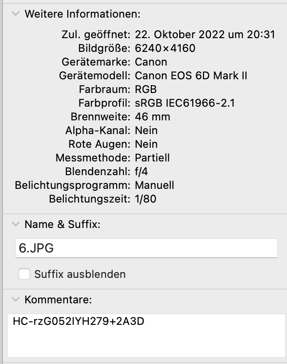
S11: Crimescene Picture 6
Crimescene picture 6 contains a flag in the comment field of the image.
Scoring
The initial scoring system was as follows:
| Flag type | Points | Amount | Sum Points |
|---|---|---|---|
| Hardware | 3 | 7 | 21 |
| Evidence | 2 | 6 | 12 |
| USB | 1 | 7 | 7 |
| Side | 1 | 10 | 10 |
| Sum | 30 | 50 |